 FREE 1 to 3-Day Delivery on Orders $149+ Details
How to Install an NX Digital Window Switch on Your 1986-1995 Mustang V8
Shop Parts in this Guide
Installation
IMPORTANT: Read the instructions before attempting the installation
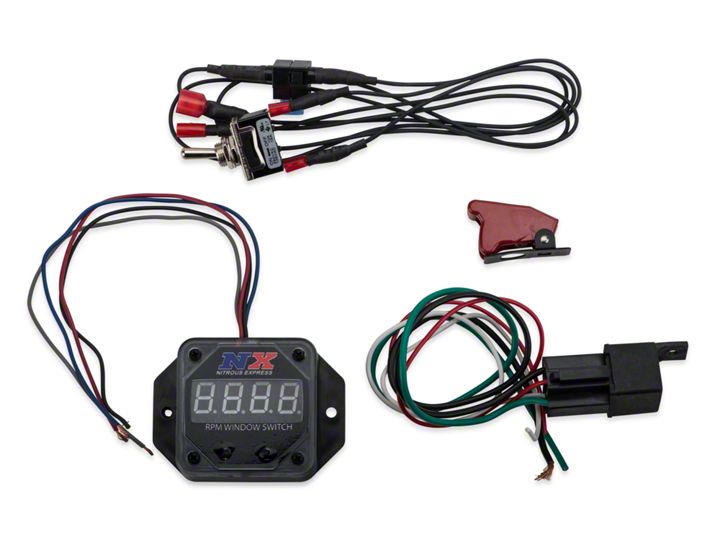
Parts Included:
1 - RPM Window Switch
1 - 3000 RPM Chip
1 - Electrical Pack
1 - 6000 RPM Chip
1 - Pigtail and Relay
NOTE: RPM Modules must be purchased separately.
The RPM Activate Window Switch can be connected to stock ignition systems or MSD Ignitions. When using a capacitive discharge ignition such as an MSD, do not connect the Switch to the coil negative terminal. Damage to the Switch will occur.
The Window Switch is capable of carrying 1.5 amps. If the circuit you are activating requires more current, an NX Relay, PN 15515 (Relay & Pigtail) or 15526 (Relay only) must be used.
The RPM Window Switch has a circuit that activates a device by providing a ground path at a desired rpm(Figure 1). The ground will be removed at a different rpm to deactivate the device. If no rpm module is installed the device will remain activated as long as the rpm is above the activation amount.
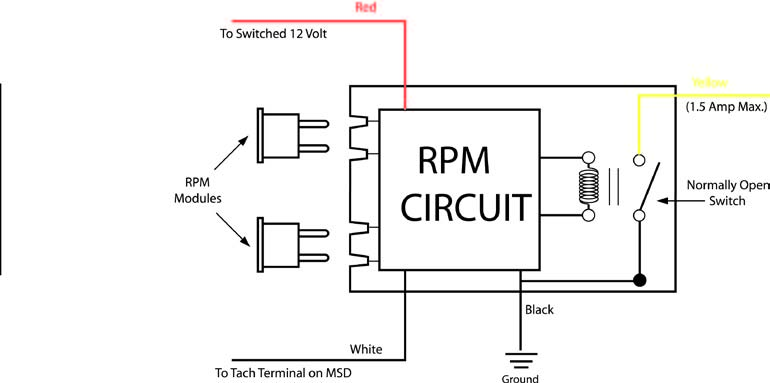
Figure 1 Operation of the RPM Window Switch
CYLINDER PROGRAMMING
The Window Switch is programmed for 8-cylinder applications, however it can be used with 4 or 6-cylinder applications. To program the Switch for different applications, the cylinder select loops must be modified as shown in Figure 2
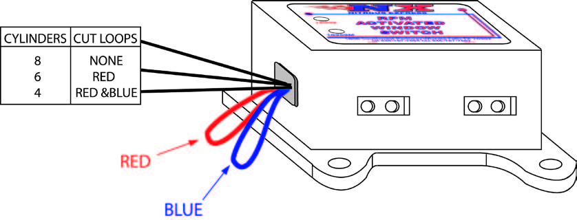
Figure 2 Cylinder Select Loops
MOUNTING
The Switch may be mounted under the hood as long as it is away from direct engine heat sources. Keep in mind that the rpm modules should be easy to access for changes. The Switch can be mounted with the double sided tape or with the 3 self tapping screws supplied. Use the Switch as a template and mark the mounting hole locations. Remove the Switch and drill the holes using a 3/16” drill bit then install the screws.
WIRING
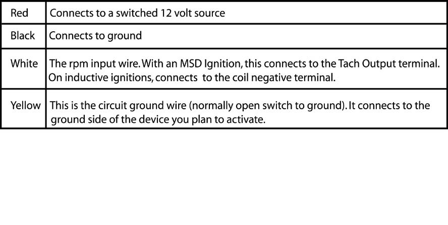
Figure 3 Wiring to an Inductive Ignition System
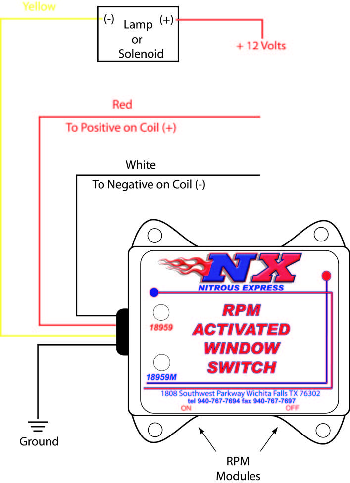
Figure 4 Wiring with an NX Relay

Related Guides
-
Installation
-
Installation
-
Installation
