 FREE 1 to 3-Day Delivery on Orders $149+ Details
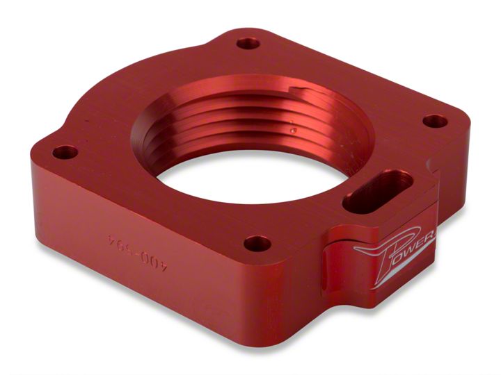
How to Install a Airaid Poweraid Throttle Body Spacer on your 1999-2001 V6 Mustang
Installation Time
1 hours
Tools Required
- 10mm Socket
- Ratchet
- 4mm Allen Wrench
- Standard Screwdriver
Shop Parts in this Guide
Installation
Parts List
- (1) Power Plate
- (2) Gaskets
- (4) 6mm x 60mm Bolts
- (4) 6mm Lock Washers
- (2) 6mm x 12 Flat Head Screws
- (1) Linkage Bracket
1. DISCONNECT NEGATIVE (-) BATTERY CABLE.
2. Remove air cleaner housing from the throttle body.
3. Remove (2) bolts and (2) studs from throttle body. (Ref. “D”)
4. Remove (2) bolts from throttle linkage bracket.
5. Remove throttle body from intake manifold; remove gasket and clean surfaces.
6. Install power plate using (2) gaskets. (Ref. “A”)
A. Place one gasket between the throttle body and power plate.
B. Place second gasket between the power plate and intake manifold.
7. Locate (1) linkage plate using (2) flat head screws (Ref. “C”); relocate the throttle linkage bracket using (2) 6mm bolts.
8. Inspect & Test the throttle linkage for full Open & Closed travel before driving. Some cruise or kickdown cables may require adjustment. Please refer to your vehicles service manual for proper adjusting.
9. Reinstall the air cleaner housing. Refer to Step 2
10. Reconnect battery cable. Enjoy!
