 FREE 1 to 3-Day Delivery on Orders $149+ Details
How to Install a CDC Shaker System on Your 1999-2002 V6 Mustang
Installation Time
3 hours
Tools Required
- Template
- Tape
- Center Punch
- 1" Hole Saw
- Saber Saw
- 1/8" Pilot Drill Bit
- 5/16" Drill Bit
- 3/8" Allen Wrench
- Scissors for cutting Template
- Drill Motor
- Phillips Head Screw Driver
- Eye Protection
- 8mm Socket
- 10mm Socket
- 11mm Socket
- ¼" or 3/8" Drive Ratchet
- T40 (Torx Bit)
- INCH LB. Torque Wrench
- Removable Loctite
- 1/2" Socket, 1/4" Drive
- 1/4" Drive Nut Driver
- 7 - M-6 Washers
- 4 - M6 - 1.0x18.5mm Hex Head Bolts
- 2 - 1/4" Washers
- 4 - #8 x 3/4" Self Tapping Screws
- 1 - Weather Seal, 60" Long
- 1 - 6mm nut
- 1 - Hood Cutout Template
- 1 - Filter Housing to Air Tube Extension
- 1 - Forward Bracket with Ball Stud Socket
- 1 - Air Filter Cover Cutout Template
- 1 - Instructions

Shop Parts in this Guide
Installation
*03 Model requires new hood
Contents w/ Kit
- 1 - Hood Appliqué
- 1 - Aluminum Shaker Scoop
- 1 - Lower Air Box w/drain tube fittings (2)
- 1 - Upper Air Box w/CDC nameplate
- 1 - Air Tube
- 3 - Ball Stud Sockets & Brackets (Y & Z)
- 1 - 2pc. Intake Bracket
- 4 - M-6 - 1.0 Ball Studs
- 1 - 3/8" ID Driver Side Drain Tube
- 2 - 3/8" Drain Tubes (18" length)
- 2 - 4.8 - 1.6 x 15mm Phillips Head Screws
- 8 - 5/16" Thread Cutting Nuts
- 3 - M-6-1.0 x 70 mm Hex Head Screws
- 1 - M-6-1.0 x 75mm Hex Head Screw
- 5 - M-6-1.0 x 10mm Hex Head Screws
Note: To ensure the quality of the vehicle and product, have your Shaker Appliqué painted by a qualified professional automotive painting facility. Product is Injection Molded ABS Plastic and recommended bake temperature is 130 degrees Fahrenheit or below.
Installing Hood Appliqué:
A. Raise Hood, Remove under hood blanket (and production hood scoop if installed on car) 7 nuts, 9mm (Figure 1)
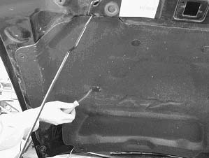
Figure 1
B. Close Hood - Align template with hood feature lines as noted on template. Tape template securely to outside hood surface (Figure 2)
**Note: Do not remove template from hood until steps A-G are complete.
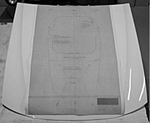
Figure 2
C. Using a center punch, transfer the (10) screw hole locations to the hood. Drill with a 1/8” pilot hole through template, hood and inner reinforcement. (NOTE: Make sure holes A, B, C, D, E are drilled through hood inner reinforcement) (Figure 3)

Figure 3
D. Raise hood – Using a 1” hole saw, drill holes called out as A, B, C, D, and E in the hood inner reinforcement. DO NOT DRILL THROUGH THE HOOD OUTER WITH HOLE SAW! . (Figure 4 & 5)
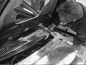
Figure 4
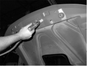
Figure 5
E. Close hood. Finish drilling the 10 pilot holes with the drill size indicated on the template.
F. Drill a starter hole for the Shaker opening with a 1” hole saw as shown on template. Use a saber saw to cut out the Shaker opening (Figure 6)
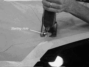
Figure 6
G. Open hood. Attach appliqué to hood using (8) 5/16" Thread Cutting Nuts and (2) 4.8-1.6 x 15mm Phillips head screws. *Use Phillips head screws at attachment points just forward of hood scoop opening.
Note: Do not over tighten appliqué bolts! *Install thread cutting nuts with a 1/2" Socket on a nut driver to hand tight ** Torque Nuts to 15 inch pounds
H. Reinstall hood blanket using original fasteners. (Figure 7)
I. Cut hood blanket to fit appliqué opening. (Figure 7)
J. Install weather strip and cut to size to opening as shown. Weather strip sandwiches appliqué, hood, outer and blanket together. (Figure 7)
**Note: Bulb on seal should be on outside of opening.
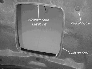
Figure 7
Assembling Air Tube:
A. Remove stock air filter and rubber air snorkel housing from vehicle.
B. Grind fins from air filter housing, starting at top clamp remove 6 fins leaving 2.
C. Cut out air filter housing template.
Note: Follow instructions on template
D. Place template on air filter housing following instructions.
E. Mark hole location onto air filter housing and cut out as shown.
F. Drill a 5/16" hole in bottom o stock air filter housing at its lowest point for drainage.
G. Attach Shaker Air Tube extension to air filter using 4 self tapping screws. (Figure 8)
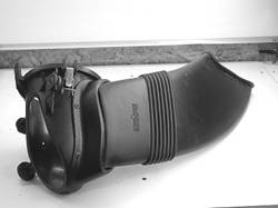
Figure 8
H. Attach Air Tube to extension, fit is tight, use care.
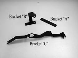
Figure 9
Mounting Shaker Air Box:
A. Attach bracket "C" to alternator bolt and air conditioner compressor bolt (Figure 10)
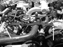
Figure 10
B. Assemble brackets "A" & "B" (Figure 10.5)
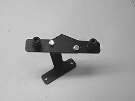
Figure 10.5
C. Attach "A" & "B" Bracket assembly to intake using factory bolts (Figure 11) Torque bolts 40-inch lbs
NOTE: Torque ball studs to 40-inch lbs.... over tightening will damage ball stud
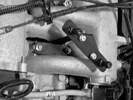
Figure 11
Shaker Air Box Assembly:
A. Loosely install Z brackets with ball stud caps to lower air box using M6-1.0 x 18.5mm bolts. Install ball stud with M6-1.0 nut (DO NOT TIGHTEN) loosely install "y" bracket with ball stud cap to lower air box using M6-1.0x10mm hex head screw with 6mm flat washer (Figure 12)

Figure 12
B. Place upper air box and aluminum scoop onto lower air box (no hardware) and snap unit to brackets on motor by firmly pushing onto ball studs (Figure 13)
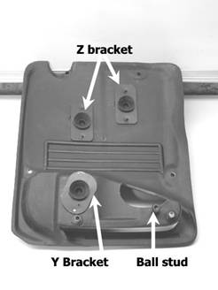
Figure 13
C. Close hood gently and align Shaker scoop in center of hood opening.
D. Once the aluminum scoop is aligned, with the hood closed, remove only the aluminum scoop from the upper air box and tighten brackets Y and Z and ball stud nut (Figure 14 )
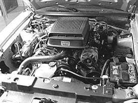
Figure 14
E. Open hood to remove the entire Shaker air box assembly from motor brackets.
F. Assemble Shaker aluminum scoop to upper air box using two M6-1.0 x 10mm bolts. (Figure 15)
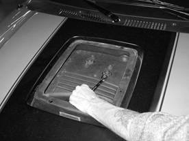
Figure 15
G. Assemble lower air box to Shaker aluminum scoop using three M6-1.0 x 70mm and one M6-1.0 x 75mm. (Figure 15 ) DO NOT OVER TIGHTEN. Snug two rear bolts, all other bolts tighten to 25 inch pounds, use thread locker
H. Install stock air filter housing with Shaker air tube and extension back into vehicle.
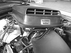
I. Slide entire Shaker air box assembly onto the air tube already assembled in vehicle. Once air tube is inserted into the Shaker air box, snap air box assembly down onto ball studs to lock in place (Figure 16)
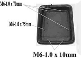
Figure 16
J. Attach drain tubes to Shaker Air Box assembly.
DRAIN TUBES:
Route drain tubes, down each side of motor. Be sure to avoid all hot and moving parts of the engine secure drain tubes to hose fittings with tie straps.
Final
Thank you for choosing Classic Design Concepts for your restyling needs. If you have any questions or concerns regarding in
