 FREE 1 to 3-Day Delivery on Orders $149+ Details
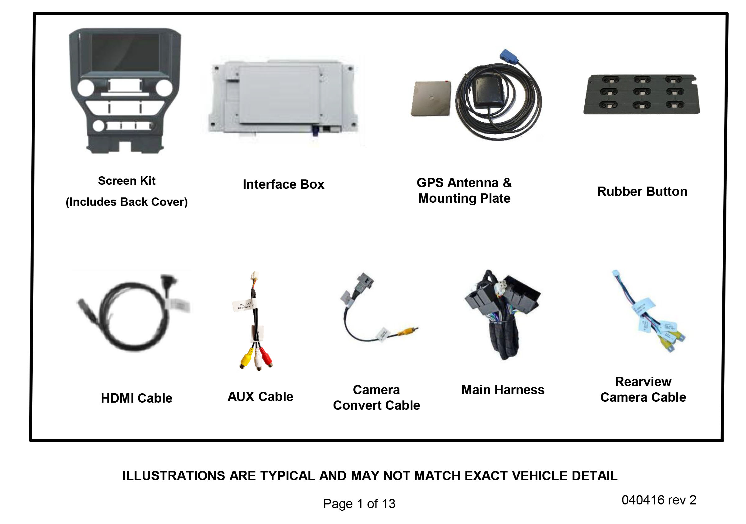
How to Install your Raxiom Navigation & Touch Screen Upgrade for OE Radio (15-17 All)
Installation Time
3 hours
Tools Required
- T-10 Torx Driver
- Trim Removal Tool
- Towel
- 7mm Nut Driver
Important
Please read and follow the instructions carefully. To emphasize special information, the symbol and the words Warning, Caution and Note have special meanings. Pay special attention to messages highlighted by these signal words. 040416 rev 2 Preparation
Prior to Installation Tools Needed 1. T-10 Torx Driver 2. Trim Removal Tool 3. Towel 4. 7mm Nut Driver Consult Vehicle owners guide before disconnecting negative battery cable. NOTICE These instructions are designed as a guide to help make the installation of this product successful. Always use caution and ask for assistance if you are not sure how to proceed. Raxiom is not responsible for any damage that may occur during installation or any changes to the vehicle interior
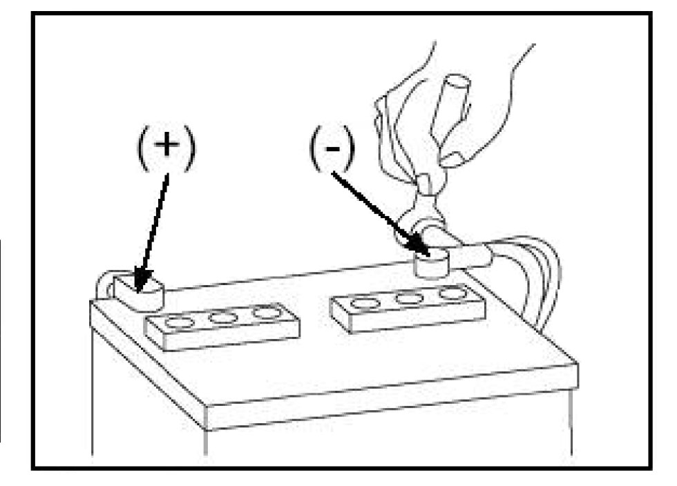
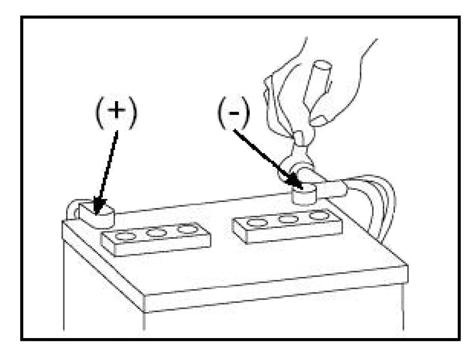
Consult Vehicle owners guide before disconnecting negative battery cable. Do not touch the positive terminal with any tool when removing the negative battery cable. This is a potential hazard that could result in vehicle or equipment damage.
Prior to Installation:
Cover all surfaces with tape or plastic protection film to protect against scratching and damage. raxiom is in no way responsible for any damage that may incur during installation.
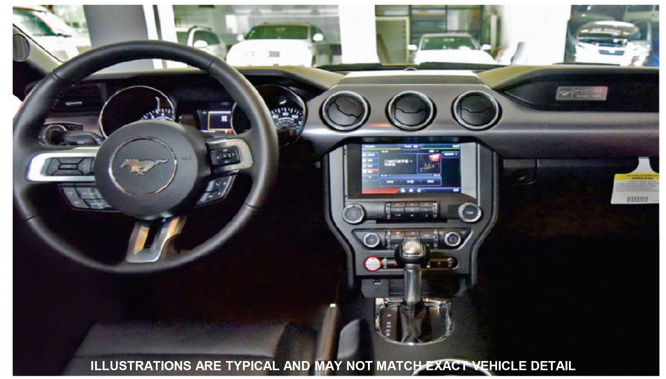
This product has been validated in the vehicles listed on the application guide only.
Care must be taken when installing this accessory to ensure damage does not occur to the vehicle. The installation of this accessory should follow approved guidelines to ensure proper installation. Read entire instructions thoroughly before starting.
This document covers such items as:
• Vehicle Protection (use of covers and blankets, cleaning chemicals, etc.).
• Vehicle Disassembly / Reassembly (panel removal, part storage, etc..).
• Electrical Component Disassembly / Reassembly (battery disconnection, connector removal, etc.).
NOTES: Removed Parts: Inspect the vehicle and parts for any damage. Place all removed parts on a protected surface in an area where they will not get damaged. Connectors: When disconnecting connectors, do not pull on the wires; pull by holding the connectors.
Vehicle Preparation and Protection CAUTION! Consult your vehicle owner’s manual to disconnect the battery. Do not disconnect ANY airbag connectors or indicators. Doing so may result in activating a diagnostic code. These codes will require the dealer to perform the reset procedure which may incur a reset fee. If you are unsure of any vehicle trim removal process consult the OEM service manual.
Removing vehicle trim panels in extreme hot and or cold climate could result in damage. Use care when removing all vehicle trims. Using painters Blue tape on the vehicle trim panels can help limit any scratches and / or marring. Use a nylon trim panel removal tool whenever possible.
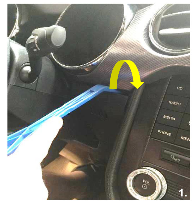
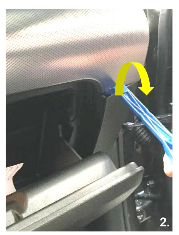
Remove the dash piece from between the center console and the steering column. Recommended tool (Nylon pry tool)
Remove the dash piece from the passenger side next to the glove box.
Recommended tool (Nylon pry tool)
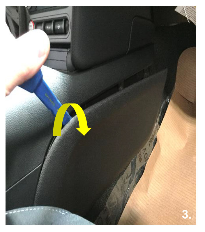
Remove the lower portion of the center console from both passenger and driver’s side.
Recommended tool (Nylon pry tool)
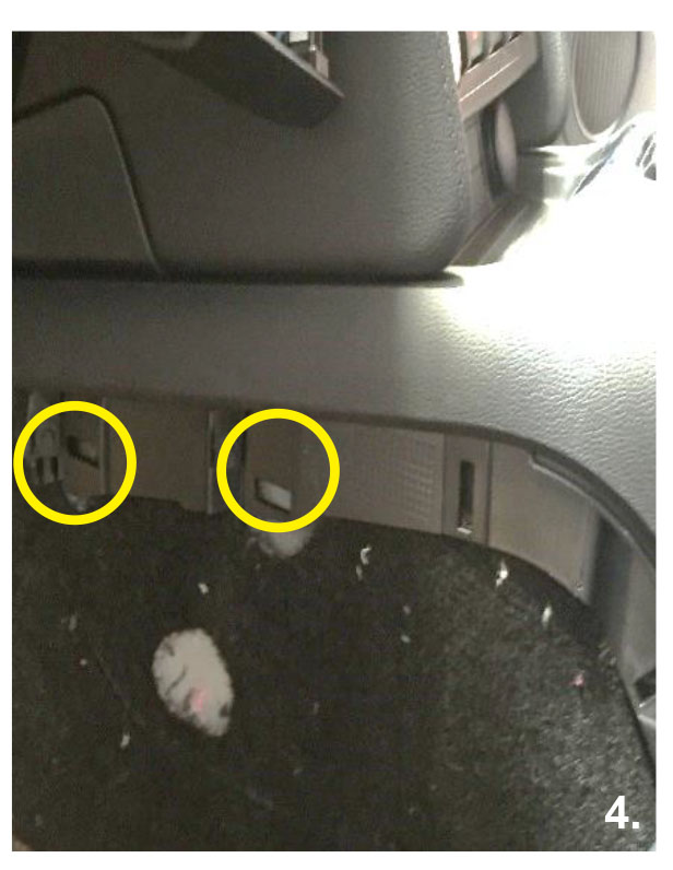
Remove the four 7mm screws that hold the center console in place from both passenger and driver’s side.
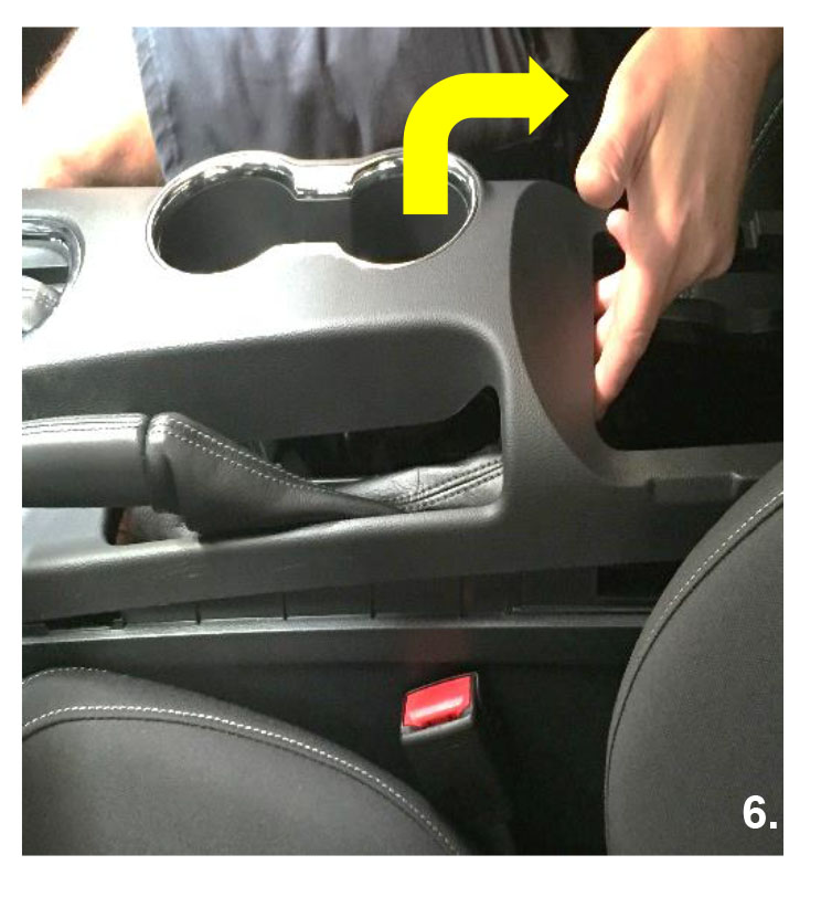
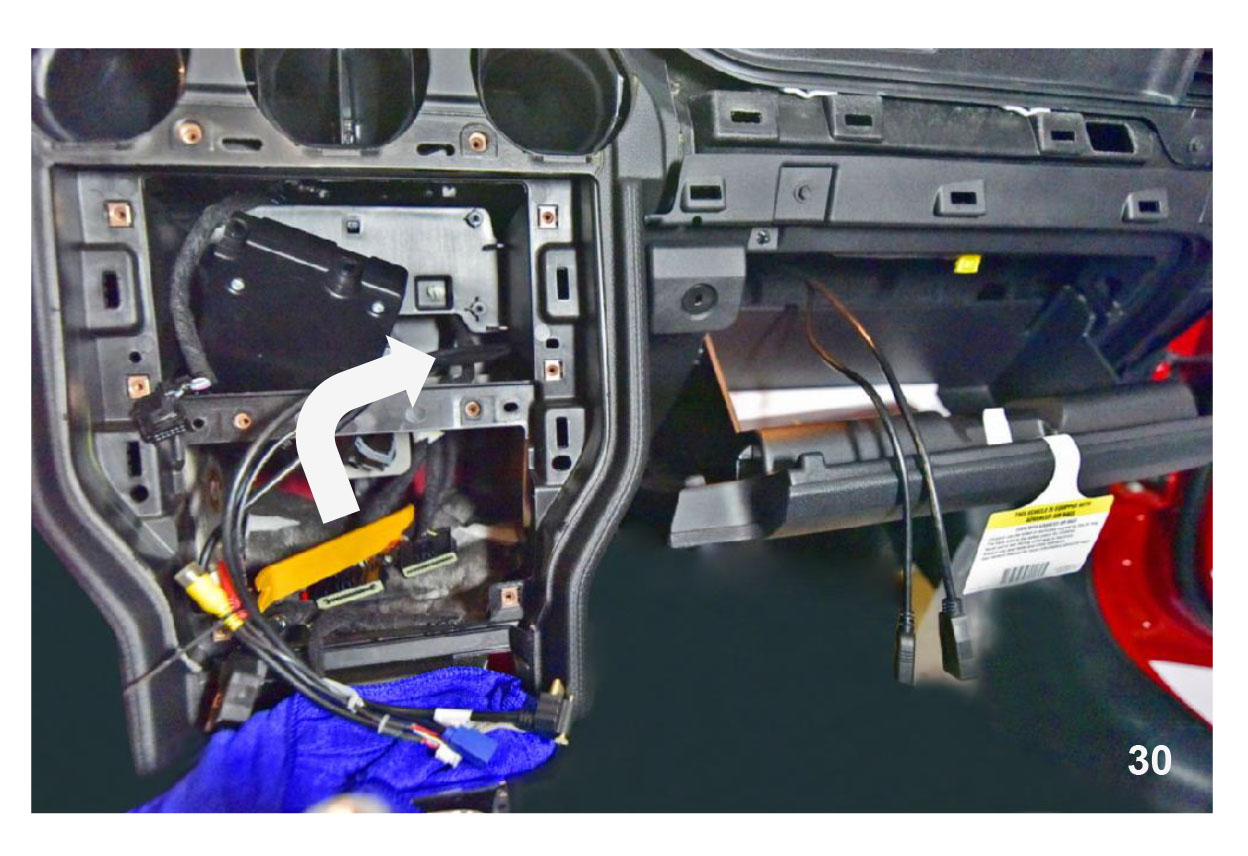
Carefully pry up the center console from inside the rear glove box. Recommended tool (Nylon pry tool)
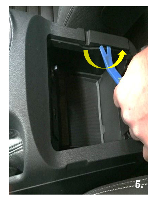
Carefully pry up the center console and pull it slightly towards the rear of the vehicle. Console will only move approximately 1 inch Recommended tool (Nylon pry tool)
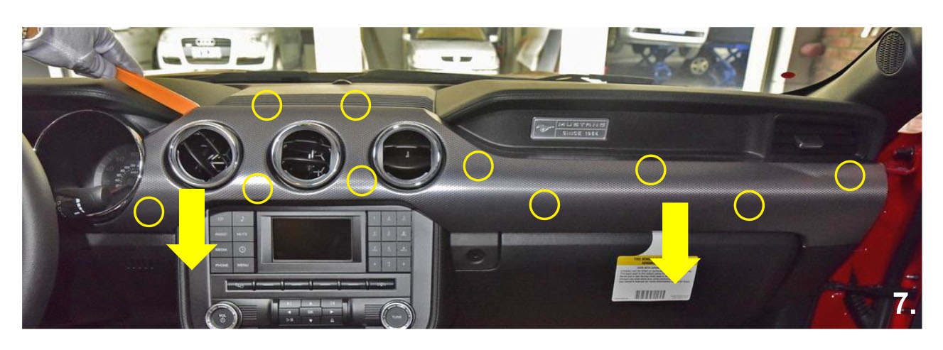
Remove the vent covers from the top portion of the dash board. Pry towards the rear of the vehicle. Recommended tool (Nylon pry tool)
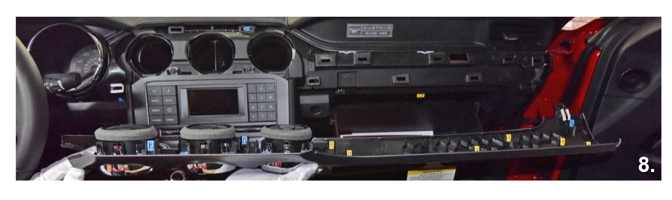
Once dash piece is removed, place in safe area to avoid damage.
Remove the rubber cover from the small pocket in the front of the center console. Remove the two 7mm screws holding the plastic pocket in place. Then remove the plastic pocket.
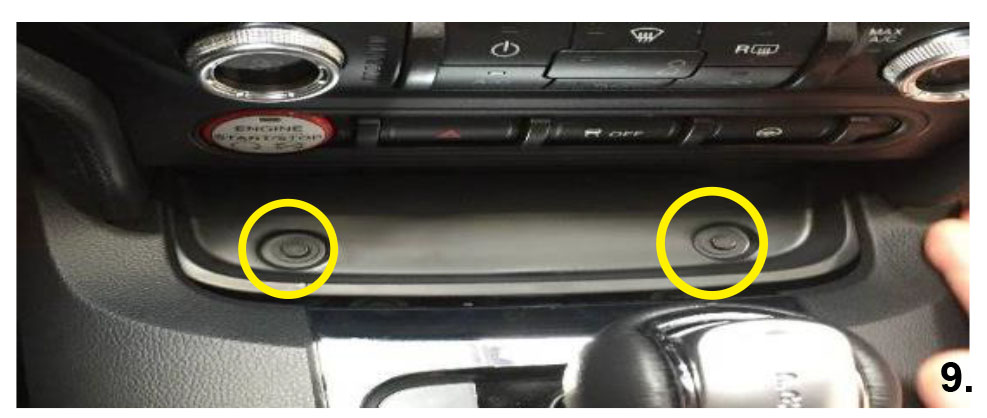
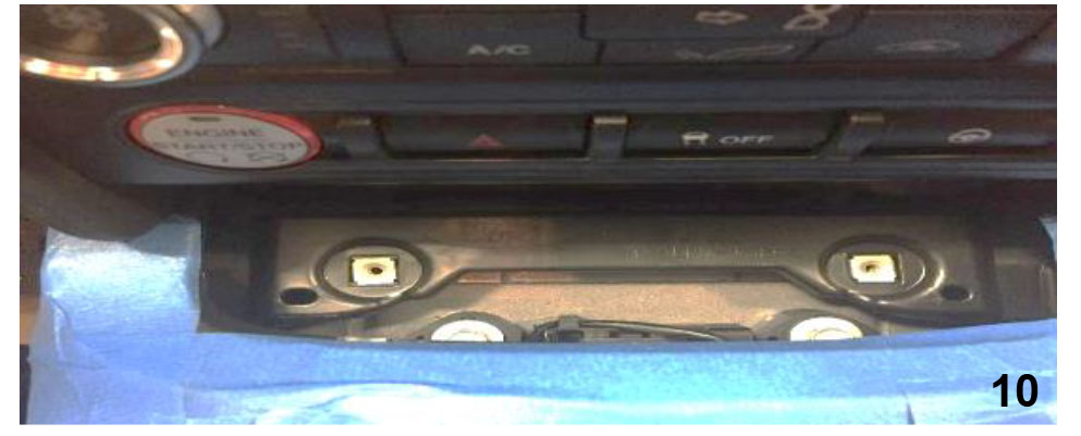
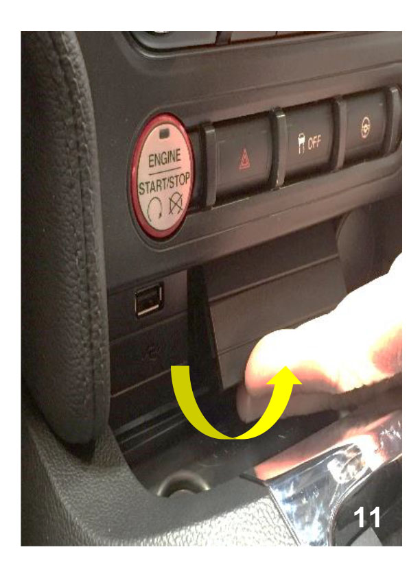
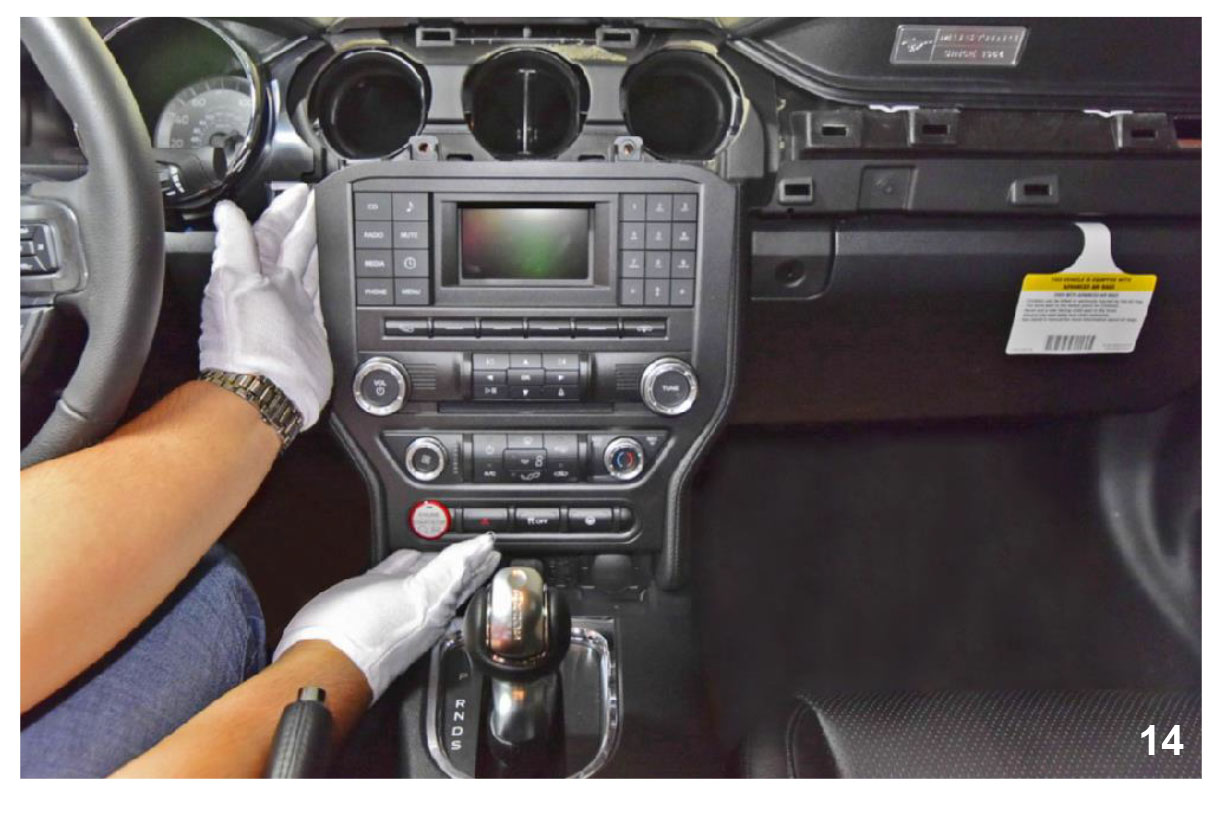
Remove the plastic cover located below the HAZARD flasher button by pulling towards the rear of the vehicle from below.
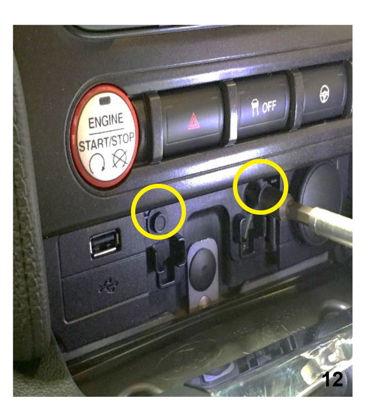
Remove the two 7mm screws located behind the plastic cover.
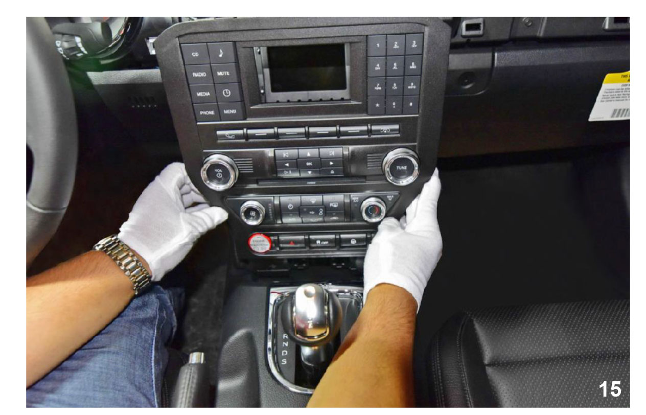
Remove the two 7mm screws above the radio. Pull the radio panel from the top towards the rear of the vehicle. Disconnect all the connectors behind the radio.
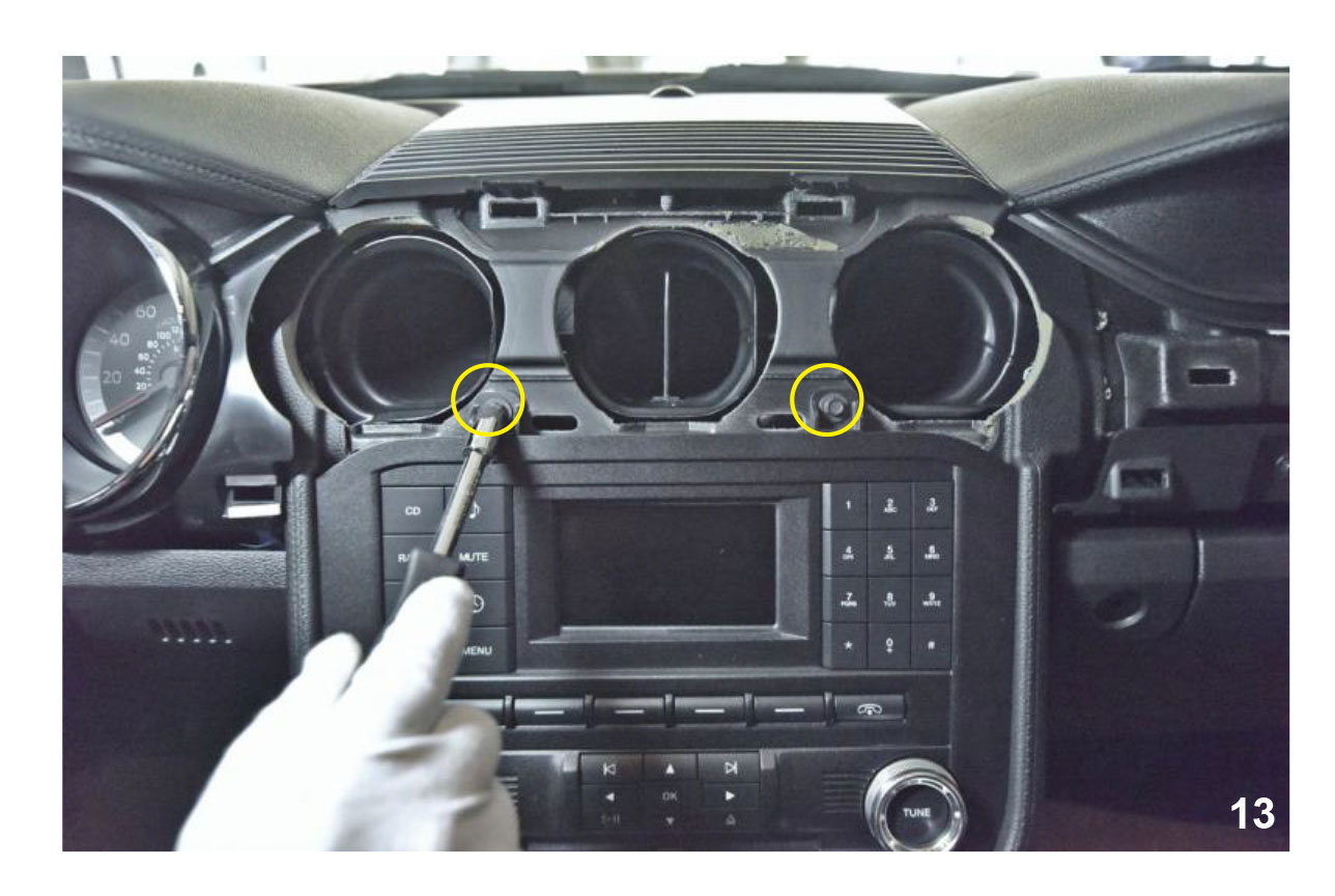
Once all the connectors are disconnected remove the radio panel by lifting up and towards the rear of the vehicle.
NOTE: Unit will fit tightly in the vehicle.
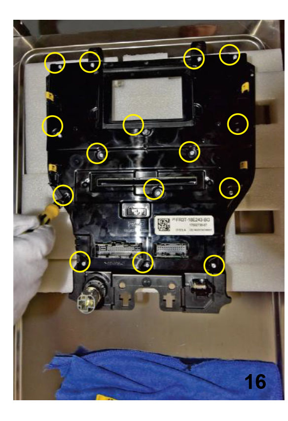
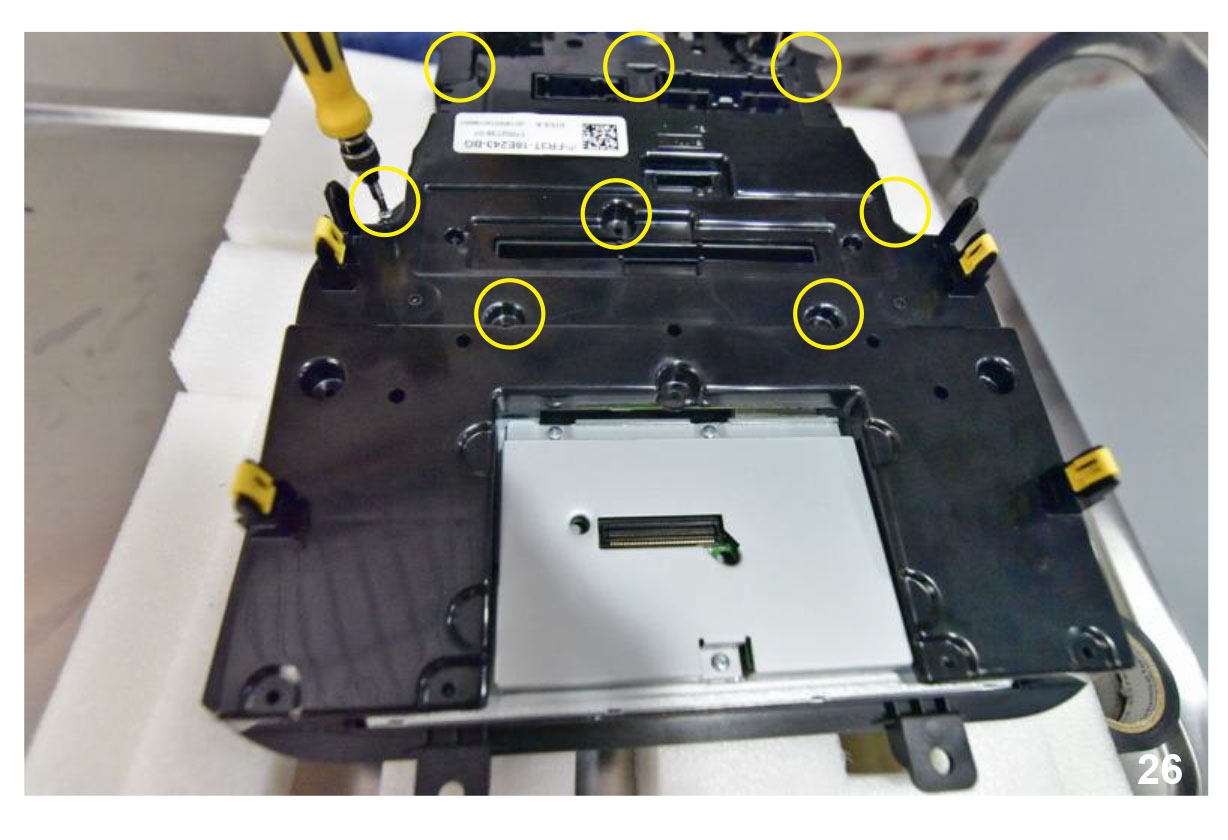
Remove the fourteen T-10 Torx screws from the back of the radio to expose the green PC board. These screws are longer than the ones in the next step. (Do not get them mixed up. Doing so can damage the front of the radio.)
Remove the seven T-10 Torx screws from green PC board on the radio.
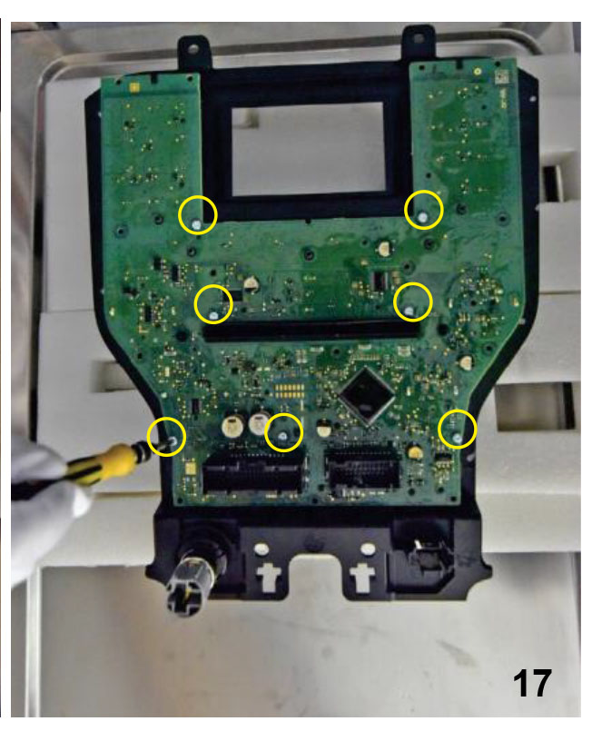
Caution
The screws are different sizes Longer screws are from the back outer part of the radio.
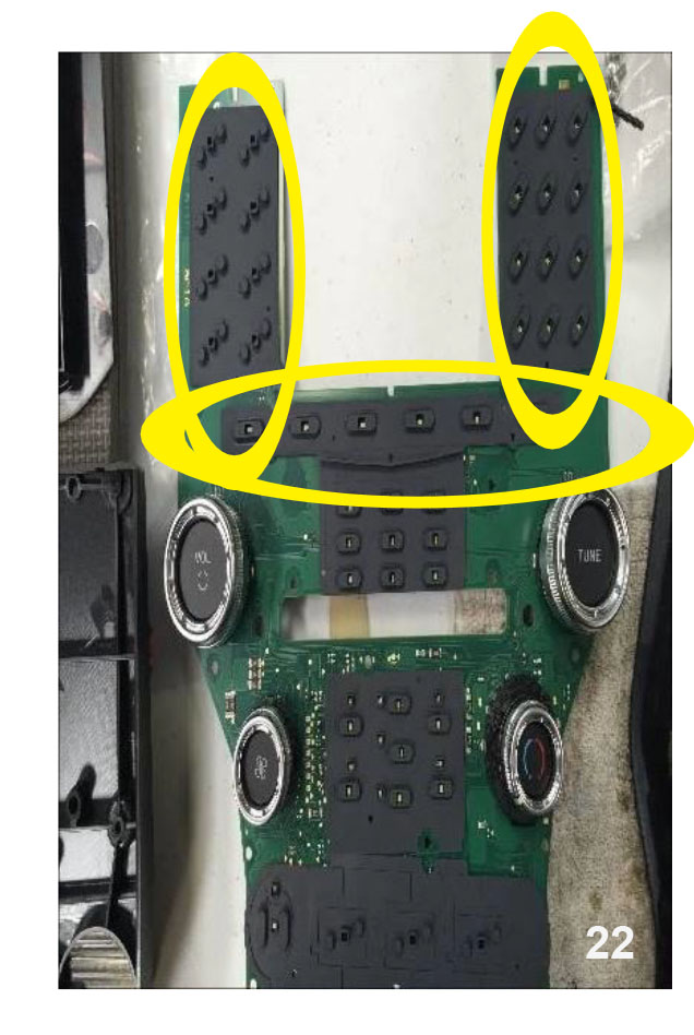
Remove all the buttons and the rubber backing. Pay close attention to the order they are removed. They will need to be inserted in the reverse order on the new panel.
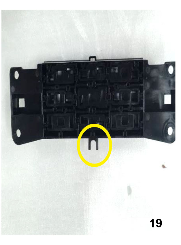
Trim the locating tabs off the controls for the radio before installing it into the new dash piece.
Remove the felt carefully from the CD slot.
Remove the frosted insert for the CD slot. This will need to be installed on the new radio dash piece
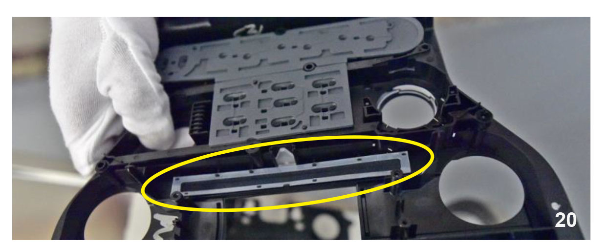
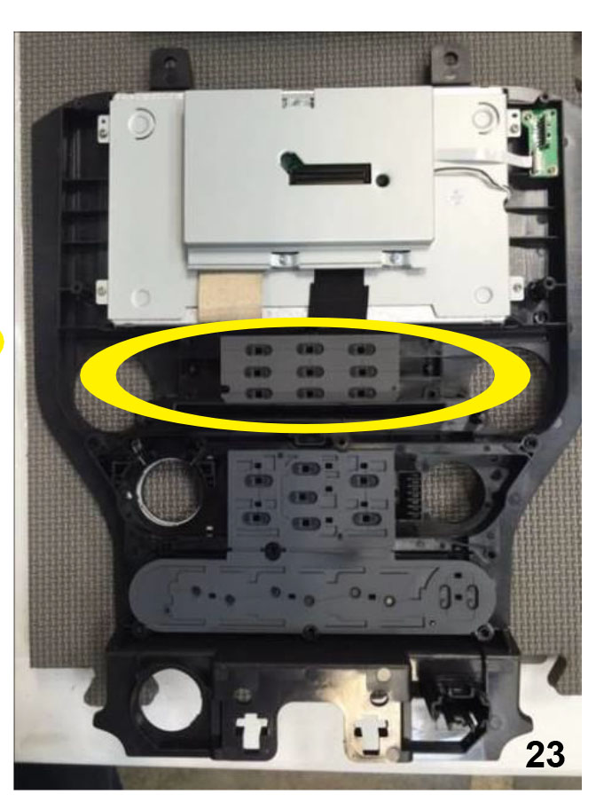
Remove the three rubber buttons. NOTE: These will not be reused
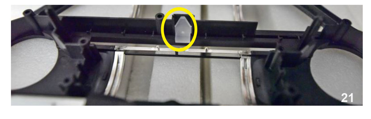
Replace the one rubber button below the screen with the rubber buttons supplied.
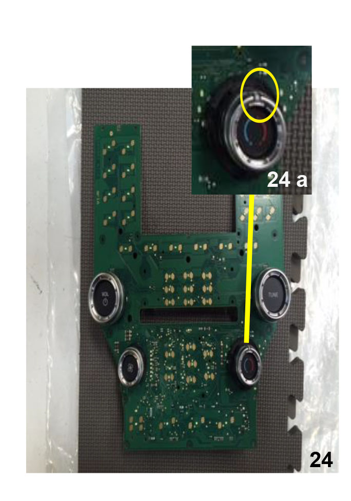
Make sure the Hot/Cold dial indicator is set to the center before installing.
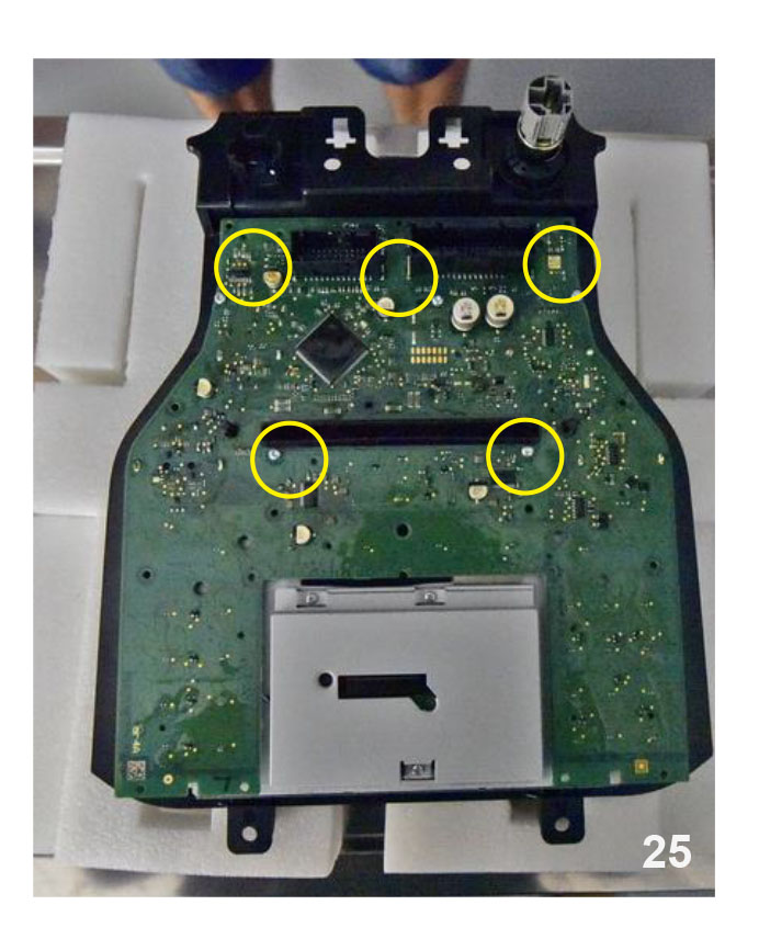
Reinstall the green PC board on the new radio dash piece. Use the shorter T-10 Torx screws.
NOTE: Two of the screws will not used in the new dash piece
Replace the rear cover with the supplied piece.
NOTE: Three of the longer T-10 Torx screws are not used. The four screws around the top are installed in the next step. Check the knobs on the front to make sure they are still movable. If not remove the screws and check alignment of the knobs.
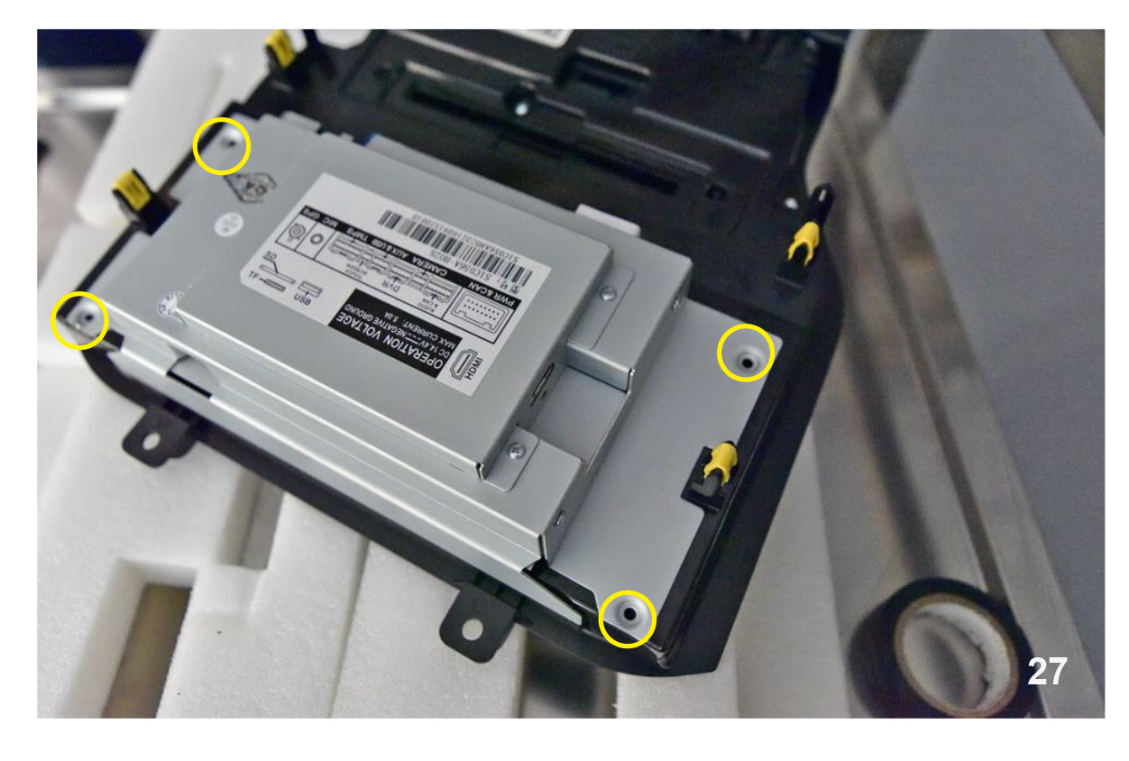
Install the interface box on the back of the radio panel. Be sure to fully seat the plugs . Use four T-9 Torx screws to secure the interface box.
NOTE: DO NOT OVER TIGHTEN THE SCREWS
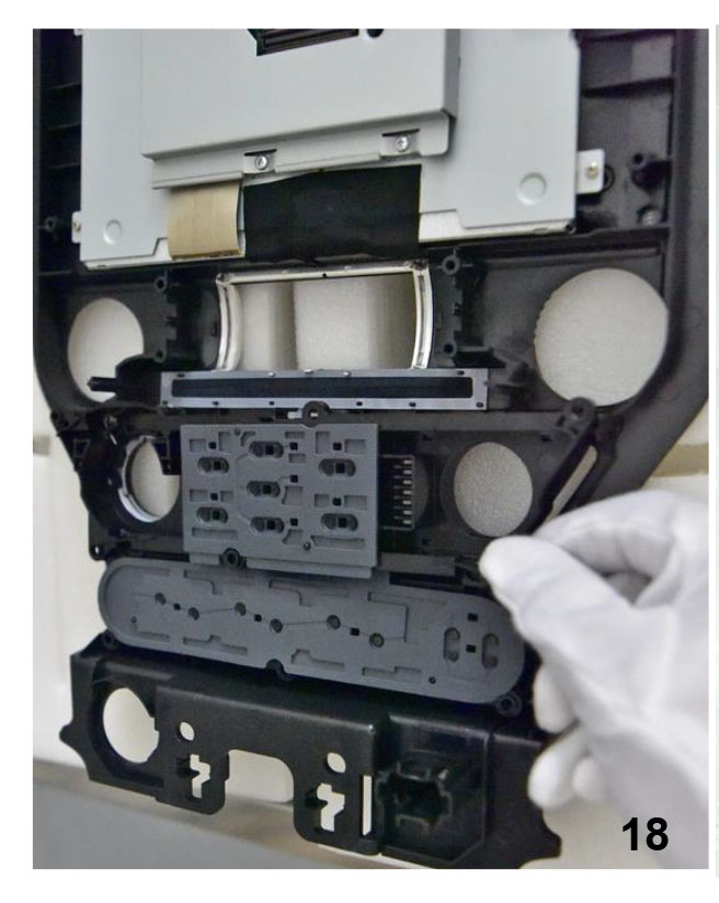
Remove the eight 7mm screws around the radio display and the CD portion of the radio.
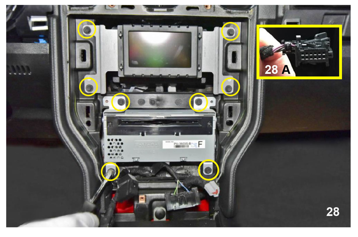
Remove the display and place in safe area. The connector behind the display is used for the rear view camera.
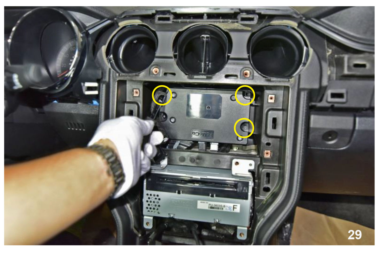
Remove the three T-9 Torx screws holding the SYNC module behind the display. NOTE: Do not remove. This is just to give you easier access to the connectors behind the CD portion of the radio. Remove the CD portion of the radio and disconnect the three connectors behind this unit.
Route the HDMI cable into the glove box.
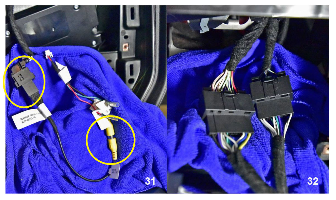
Connect the rear camera input to this connector.
Connect the supplied T-harnesses to the connectors that were behind the CD portion of the radio.
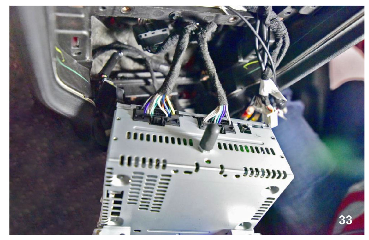
Connect the other end of the supplied T-harness to the CD portion of the radio. The lose connectors must be routed behind the cross member up near the SYNC box to be connected to the new radio dash panel. Reinstall the dash using the four 7mm screws.
NOTE: Do not forget to reconnect the antenna.
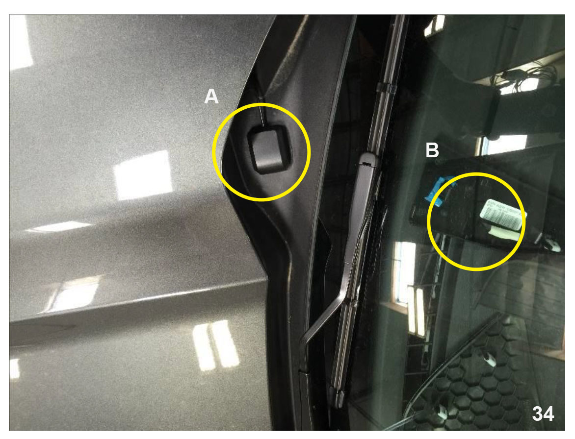
Highly recommended for the optimum performance, mount the GPS antenna outside the vehicle with an unobstructed view of the sky. (A) The antenna can be mounted on the center of the dash board with a clear view of the sky.
NOTE: There can be some reception issues with this method since the roof may interfere with the signal. (B)
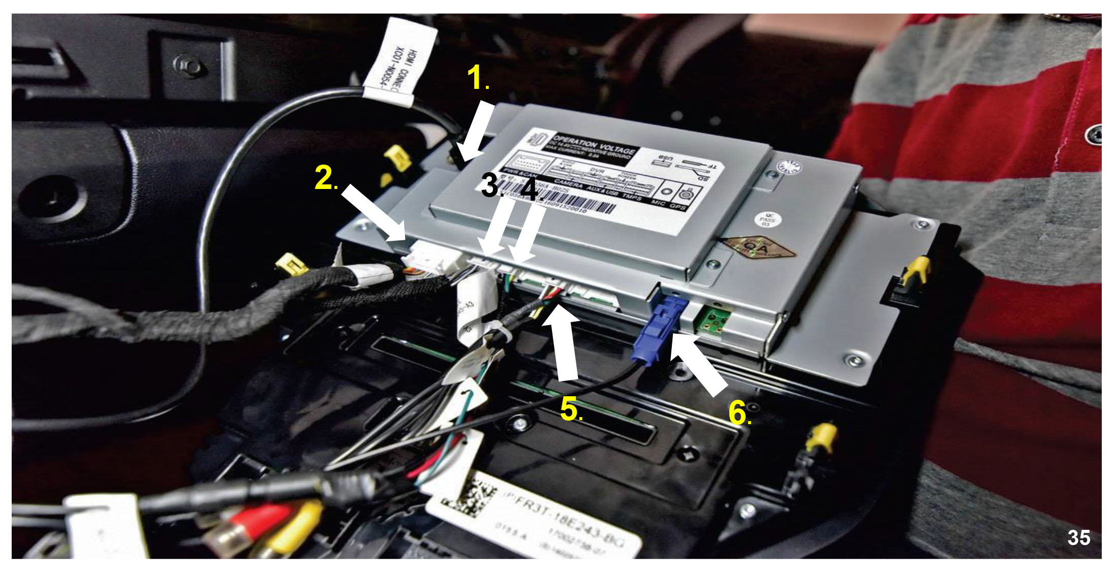
1. HDMI Input
2. Power Input
3. Audio Input
4. Camera Input
5. USB Input
6. GPS Antenna Make sure all connectors are fully seated and locked into place.
Install in the dash of the vehicle Make sure not to pinch any wires and obstruct the CD inlet.
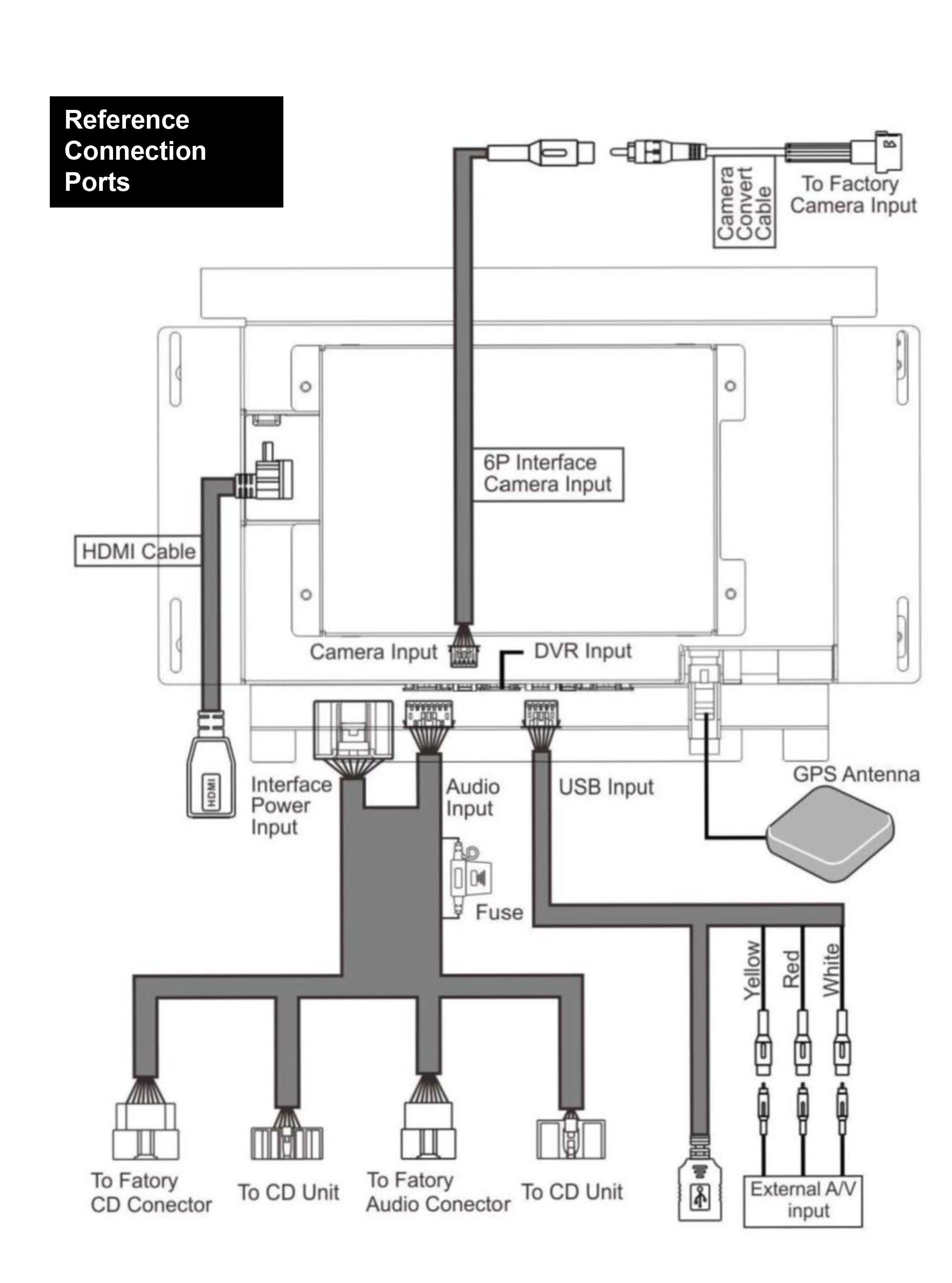
Connect ALL the harnesses to the unit. Ensure ALL the harnesses are connected to the correct ports.
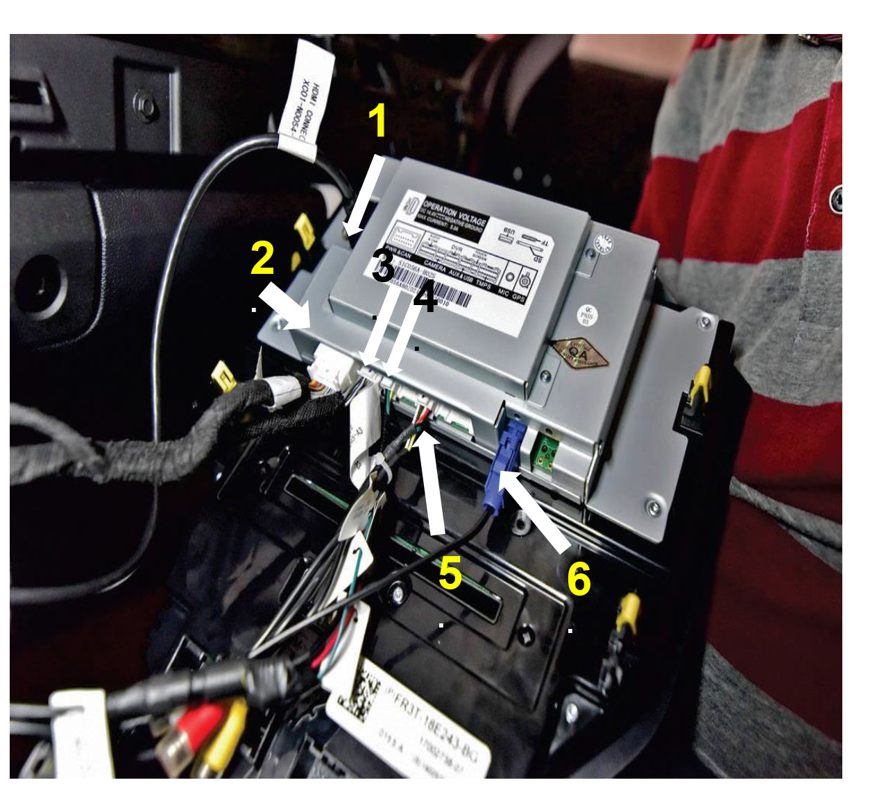
1. HDMI Input
2. Power Input
3. Audio Input
4. Camera Input
5. USB Input
6. GPS Antenna Make sure all connectors are fully seated and locked into place.
Double check all connections. Install the Navigation unit in dash . Use caution to ensure no wires are pinched or trapped behind the brackets when installing the unit into the dash. Connect and reinstall all removed panels.
Testing
Reconnect the negative battery cable. Turn the ignition switch to ON when the display of the navigation unit comes on follow the steps for set up. Place your foot on the break and place the vehicle in reverse. The rear camera will display on the screen.
NOTE: Only if camera is installed and activated. Place the vehicle back in park to go to the source selection screen. Ensure all components are in working order (Navigation, steering wheel controls, HVAC, dome lights, etc.)
Note: Check to ensure the Navigation unit, steering wheel controls, GPS signal strength and the FM tuner are properly working. Double check all the functions of the vehicle are working correctly.
Note: If the Navigation unit does not power up • Check the vehicle’s fuse first • Check that the connectors on the back of the navigation unit are fully seated and locked. • That no PINS have gotten bent in the connectors during installation.
WARNING:
Do not touch the positive terminal with any tool when reinstalling the negative battery cable.
NOTICE OF INTENDED USE Some features are not intended for viewing by the driver while the vehicle is in motion, such as any video playback. When using the navigation feature, minimize the amount of time spent on viewing the screen and use voice prompts when possible. Avoid prolonged use of the touch screen controls while the vehicle is in motion. Such use may distract the driver or interfere with the driver’s safe operation of the vehicle which can result in serious injury or death. Use of the product while the vehicle is in motion may also violate state or local laws. This product must be properly installed and used in accordance with all laws for your safety. AAMP Global does NOT assume liability for any bodily injury or property damage that might result from any improper or unintended use.
Technical Support 844-580-1799
