 FREE 1 to 3-Day Delivery on Orders $149+ Details
How To Install a Raxiom Vent Integrated OBD2 Multi-Gauge W/O Vent Housing on 2015-2016 Ford Mustang

Shop Parts in this Guide
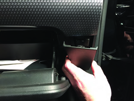
Step 1
Open glove box and remove the lower right hand trim panel. It is held in with plastic clips, rock the panel back and forth while pulling the panel straight off.
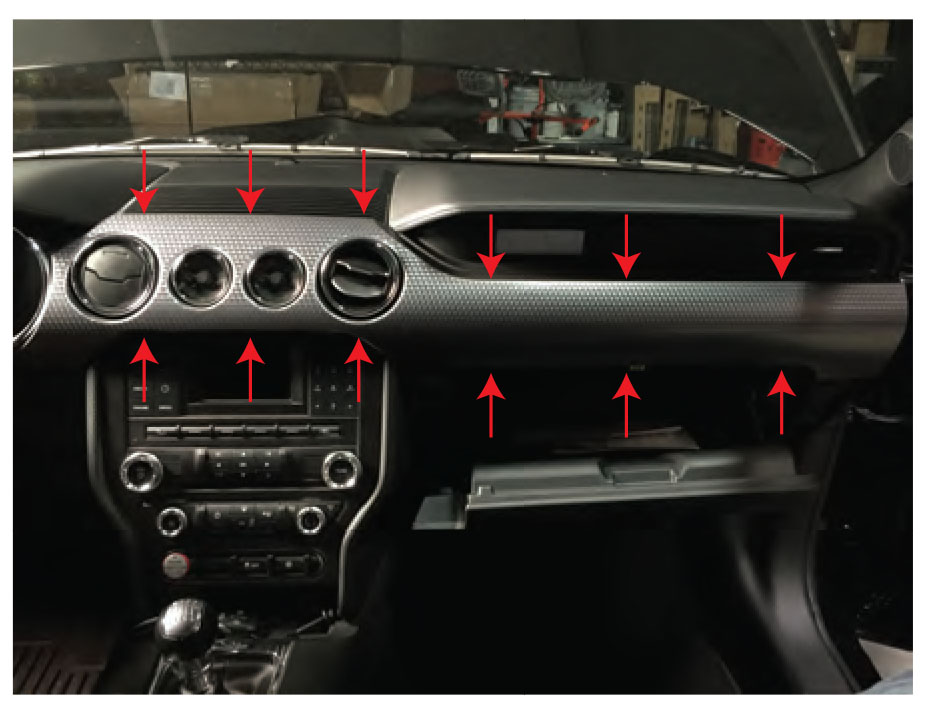
Step 2
Using the same rocking back and forth technique, remove the main dash panel.
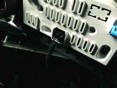
Step 3
Remove the plug on the back of the factory gauges.
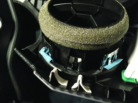
Step 4
Flip the dash panel over so you can access the back of the vent. Depress the chrome clips around the vent and push the vent through the front of the panel.
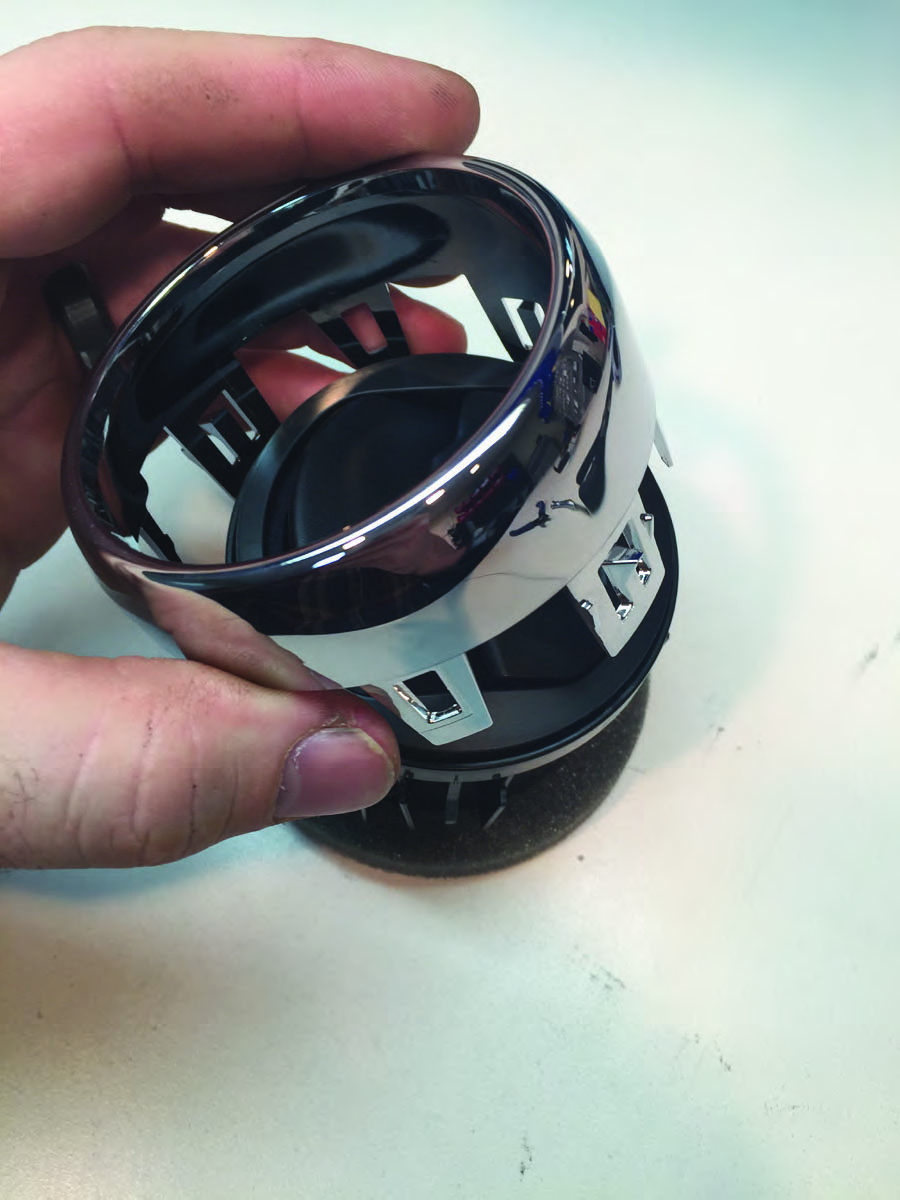
Step 5
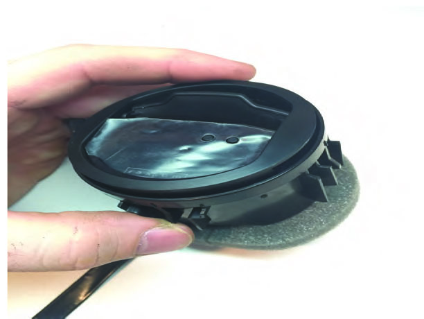
Remove the silver trim ring from the vent barrel.
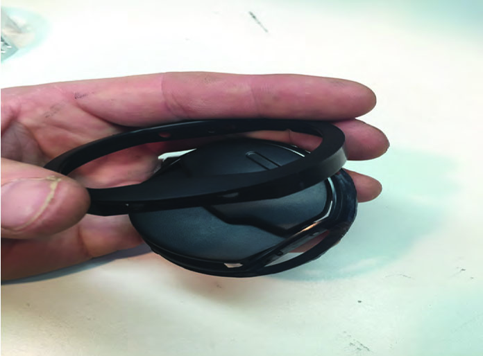
Step 6
Take the vent slat bracket out of barrel and remove black trim ring.
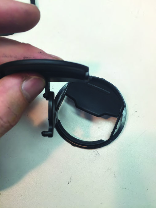
Step 7
Remove the lower vent slat and bracket.
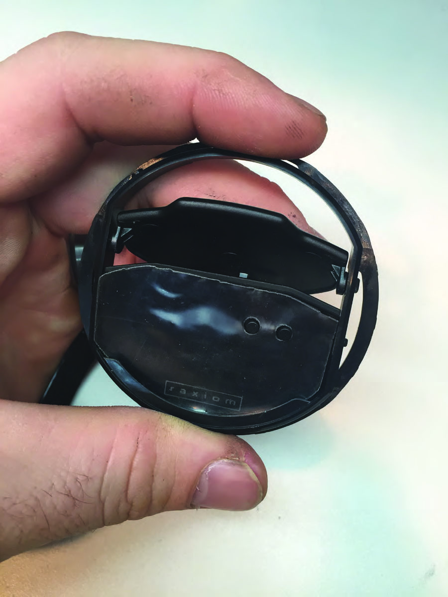
Step 8
Install display into the vent slat bracket.
**Note: Display glass goes behind lip at bottom of bracket.
Step 9
Snap the black trim ring onto the bracket and install into vent barrel.
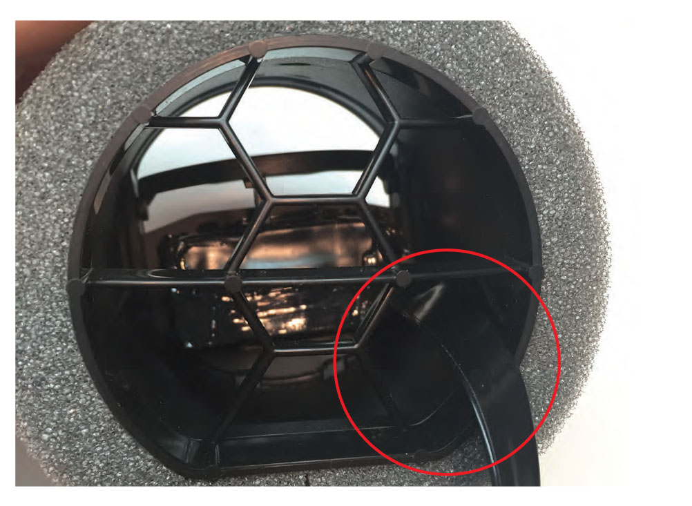
Step 10
When feeding the display cable through the back of the vent, make sure the cable goes through this hole.
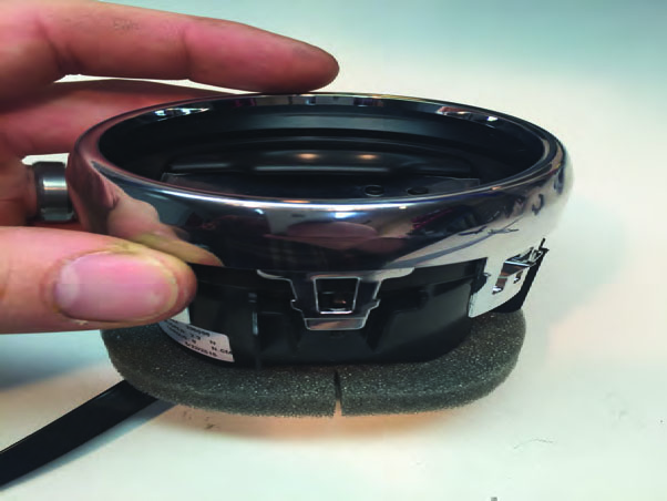
Step 11
Reinstall the chrome trim ring. **Note: The chrome ring can only be installed in one position. The tab with the two bumps lines up with the flat portion of the barrel.
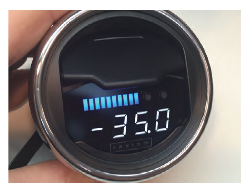
Step 12
Your gauge is now ready to be installed in your vehicle.
NOTE: Flat part of vent barrel is in the 6 o'clock position when installed in vehicle.
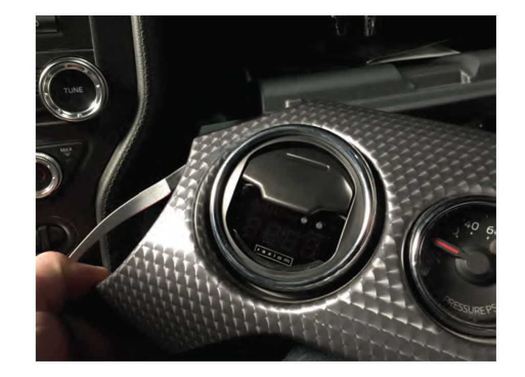
Step 13
Insert the Raxiom vent gauge by feeding the cable through the hole followed by the vent assembly. Press the vent in so that the clips clip.
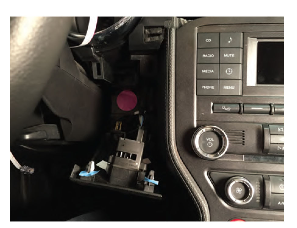
Step 14
Remove the panel on the right of the steering column, this panel is held in with clip also. Removing this panel will allow you to feed the gauge wire behind the dash towards the OBD port.
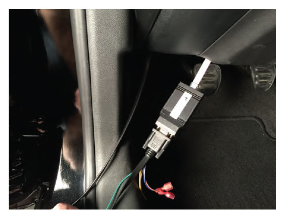
Step 15
Connect the gauge display cable to the control box. Connect the diagnostics cable to the control box and tighten. Connect the control box to the OBDII port.
Step 16
Carefully tuck all extra wiring under the dash and secure as necessary.
Wiring Details
Green - Dinner, hook to an interior lighting connection, when the headlights are on the gauge will dim.
Brown - Analog input 1
Blue - Analog input 2
Aux Plug - Analog boost sensor connection
Operation Details
BUTTON FUNCTIONS (Running Mode)
Left Button TAP = Peak recall (and start 15 second record)
Left Button HOLD = 15 sec playback
Right Button TAP = View Current Mode Name, Change Mode
Right Button HOLD = Night/Day Dimmer toggled (if auto-dimming is NOT enabled)
Available Readouts
Boost: This mode will show vacuum and boost. Depending on settings in the config menu this may be from ECU data or an external analog sensor, or MAP. Boost is read in PSI by default and Vacuum is inHg. If you configure the gauge to metric boost/vacuum will be in BAR.
Coolant: Coolant temp. Unlike the needle on your dash, this will show you exactly the temp that your engine is currently running at, and is configurable between Celcius & Fahrenheit.
Air: Air intake temperature. This is the readig of the temperature of the air entering the engine, and is configurable between Celcius & Fahrenheit. On most vehicles, this reading is taken from the T-MAP sensor on the charge pipe, before the throttle.
Igntn: Ignition timing. This mode will show you the spark timing of your engine in real-time.
Egt: Exhaust Gas Temperature. This is the temp of the exhaust gas as calculated by your ECU. (canbus vehicles only)
Throttle: Actual throttle plate position. Use this mode to see how your car changes the actual drive by wire throttle blade in relation to what your foot tells it to do.
rp-Shift: RPM readout. It can be handy to use this mode to see an exact RPM or to record/playback and see your shifts.
Speed: Actual roadspeed direct from VSS. This is the actual roadspeed value of the car, uncorrected. This is the raw value, therefore it may not match your cluster which tends to read high in many cars. This value is taken from the left rear wheel on most vehicles.
0-60: Performance Timer, 0-60 timer with auto start / stop.
Batt: Battery Voltage. This is the voltage of your car's power system, anything between 13-14.5 volts while running is normal.
Code Reading: Read and Clear diagnostic codes, this happens automatically at startup. On K-Line vehicles this is disabled by default because it delays startup.
THE PEAK RECALL AND RECORD/PLAYBACK FEATURES EXPLAINED.
PEAK RECALL: The gauge offers peak recall of the PEAK VALUE on the selected mode, since the last recall, or since the vehicle was started. In addition to this, for 2008 model year cars the gauge also stores peaks for EGT, Air, Coolant in the background, so that you can switch to that mode later, after a lap for example, and recall your peak temperatures. A quick tap of the Left most button will show your peak value.
RECORD/PLAYBACK: The 15 seconds record/playback feature is available on canbus vehicles only, and provides a way for you to see 15 seconds of historical data from the current mode. Recording is started when the peak recall button is pressed. Simply tap peak recall, do some acceleration, and then after you are able to look at the gauge again, hold the peak recall button and the gauge will show you the first 15 seconds of data from that mode, as well as RPM scaled onto the bargraph readout.
CODE READING:
For vehicles 2008, code reading is performed automatically on startup. For pre-2008 cars, you must enable code reading in the configuration menu. Code reading at startup is disabled by default on pre-2008 model year cars because the code reading process on older vehicles can take up to 10 seconds, and it would delay startup.
CODE CLEARING:
The configuration menu (see config directions for details) contains a Clr.C option. Use this to clear codes.
The best way to clear codes is as follows:
-Start the car, Enter config menu, Go to the Clr.C option, HOLD the leftmost button til the gauge stops saying HOLD. For pre-2008 vehicles, the gauge will reset and then show CLRD, for 2008 , the gauge will show CLRD right away. For some 2014 model year vehicles, you may need to shut off the engine, but have the ignition ON before holding the button for Clr.C, but most cars let you clear codes while the engine is running.
CONFIGURING THE GAUGE
ENTER CONFIG:
Simply hold both buttons to enter the config menu, you can do this at any time! RELEASE the buttons 2 seconds after you see the word "Conf" flash on the screen.
SAVING YOUR SETTINGS:
Your settings will not be saved until you exit the config menu by HOLDING the rightmost button until the gauge turns off or resets if your car is running.
Config Button Functions:
Left Button TAP = Change Value
Right Button TAP = Peak Recall
Left Button HOLD = Change Value fast repeat
Right Button HOLD = EXIT and SAVE settings.
Configurable Parameters:
Display Options / Valet Mode
d.On = display on, normal operation, Off = Lockout / Valet, display off. Enter config with car OFF to re-enable from valet. On.A = Auto dimmer (must attach green wire to red/gray dimmer line on trunk pop switch or other locations) On.P = persistent dimmer, (stays on last setting after restarts.)
English/Metric
En.Y Y or N or b English units. N = Metric, Y = English, b = Boost only (boost in PSI, all other data in metric)
Boost Pressure Resolution
Pr0.1 0.1 or 0.5 or 1.0 decimal point. 0.1 = tenths, 0.5 is rounded to 5 tenths, 1.0 = whole numbers
Vacuum Bargraph
U.bg.Y Y or N Vacuum bargraph in boost mode - set to N for no bargraph while in vacuum
Shift Light - Gauge display will FLASH when above this RPM
SL.57 . 30-99 Shiftlight activation RPM x 100, default is 5700
Boost Reading Selection:
FORD bSt.d for MAP sensor, analog. (Analog is for gauges with boost sender and tubing to manifold using the analog boost sensor connection)
Analog Input Config (see the analog inputs section for details):
A1.N Y or N Enable or disable the first analog input (brown wire)
A2.N Y or N Enable or disable the second analog input (blue wire)
Code Clearing
Clr.C Hold the first button to clear codes. See Code Reading and Clearing section above for details.
Code Reading (K-Line vehicles only)
rd.C.n, n = no code read, Y = read at startup
Analog Boost Sensor Calibration (required after install of sensor!)
Cal.b, Calibrate the analog boost sensor to your barometer. - tap left button after confirming the engine is off. Calibrate your analog sensor any time that your altitude changes significantly to ensure the highest accuracy.
Car Selection (not available on all models)
Car.0 through Car.8 and ANLG (analog) mode. See the CHART above for more details.
NOTE: For BMW models, car selections 5 through 8 cause the bSt.A mode to expect MAP sensor 0-5v input on the blue wire. If you have a bSt.P option, this does that instead of Car selection. The default setting for this value will change depending on the gauge model that was shipped. Use Car.0-5 bSt.A for analog boost sensor for this reason.
ANALOG INPUTS
The Raxiom harness has 3 linear analog inputs, 2 of which can be used as universal displays for ANY 0-5v sensor with a linear ascending output. The 3rd is used for the Analog Boost Sensor. Do not hook up a device that sends more than 5 volts or you WILL damage the control box.
5v POWER SOURCE:
If your sensor requires a 5v power source, you can use the PURPLE wire on the gauge harness.
To enable an analog input, enter the config menu and set the A1 input to Y for yes.
After doing this, 3 new options will appear:
A1.DP, analog 1 decimal points.
The gauge will show 999 on the screen, and tapping the first button will move the decimal point.
A1.Lo, analog 1 Low volt
Ov reading which the gauge will show when it sees ZERO volts on the input. -999 through 9999
A1.Hi, analog 1 High volts
5v reading, which the gauge will show when it sees FIVE volts on the input. -999 through 9999
A1.bL and A1.bH, limits of the bargraph for that input.
L is the bargraph start, H i the bargraph end.
You can leave these the same, or shrink the range for better visibility.
EXAMPLE CONFIGURATION - LC-1 / LC-2 AFR CONTROLLER:
According to the LC-1 wideband controller documentation, Analog output 2 is the 0-5v output.
LC-1 = BROWN WIRE. LC-2 = YELLOW WIRE.
LC-1/2 default output is 0V = 7.35 AFR and 5V = 22.39 AFR.
To configure our gauge to show this on the first analog input, we would use the following settings:
A1.DP, 2 decimal points, 99.99
A1.Lo, 7.35
A1.Hi, 22.39
A1.bL 7.35
A1.bH 22.39
After putting these settings onto the analog input, the gauge will show proper AFR displayed in the Analog 1 gauge mode which will appear int he running mode as AN 1.
Troubleshooting Checklist
- Make sure the gauge is set to d.On ... if you set the gauge to display off (d.Off) you will need to have the car OFF to re-enter config by holding both buttons.
- Make sure the obd2 connection is secure, try unplugging and re-plugging it a few times with the car running. Some ports can be stiff.
- Check your obd2 port fuse, on a fuse chart this will usually say OBD or DLC.

