 FREE 1 to 3-Day Delivery on Orders $149+ Details
How to Install Raxiom Gen5 Tail Lights on your 2005-2009 Mustang
Installation Time
2 hours
Tools Required
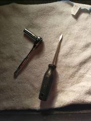
- 11mm Deep Socket and Wrench
- Slotted Screwdriver
- Clean Rag

Shop Parts in this Guide
TOOLS REQUIRED
11mm Deep Socket & Ratchet
Slotted screw driver
Clean rag
Installation Time: 60 minutes
INSTALLATION
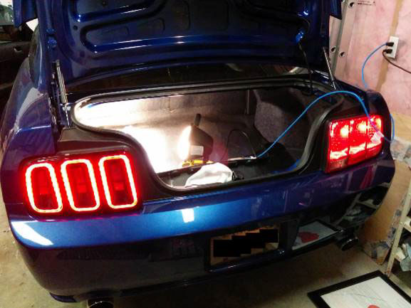
1. Once you have your new lights unpacked and ready to go, gather an 11mm socket and slotted screw driver and open the trunk.
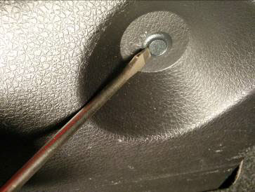
2. The plastic panel behind the tail lights is held on by several small black clips on both sides and at the bottom.
3. Take the slotted screw driver and pry out the plastic clips.
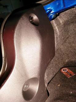
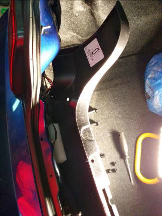
4. Once all the clips are out, the panel should tip out easily, providing access to the nuts holding the tail lights on.
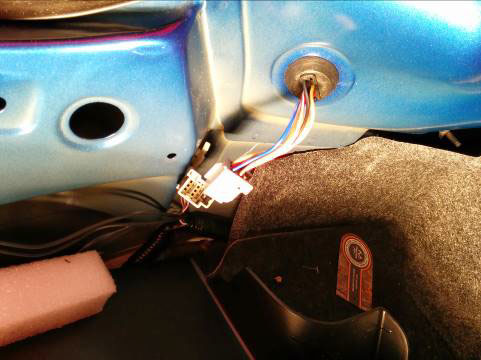
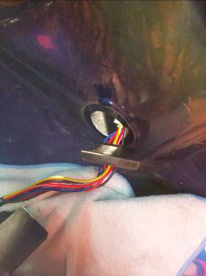
5. There are three nuts on each side holding the tail lights in. The wiring harness also passes through the body panel in a rubber grommet.
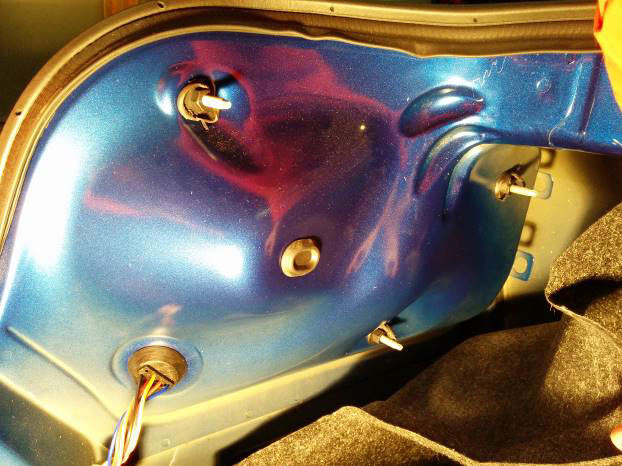
6. Take an 11mm deep socket and remove the nuts on all three bolts.
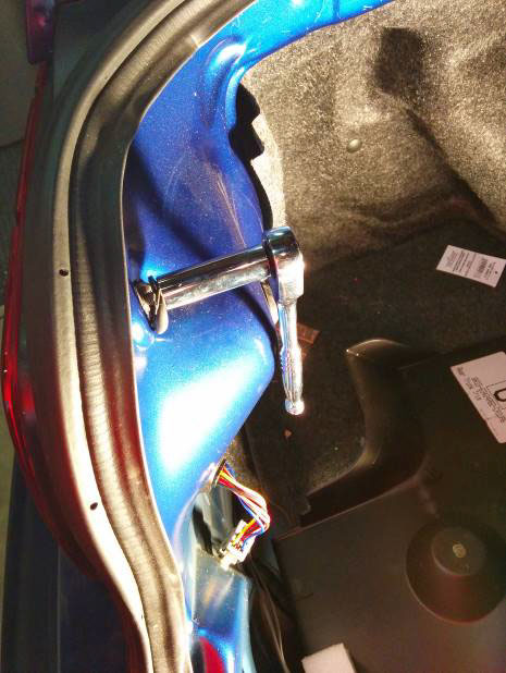
7. Slide the tail light unit out of the car. It might take a little effort. Take care not to scratch the paint (this is where the clean rag comes in… you can rest the tail light on the rag). After disconnecting the wire clips, you can carefully push the rubber grommet of wires out.
8. Slide the old light out and the new light in. It will probably be a snug fit, and it may take some effort.
9. Once the new light housing is in, feed the new wires through the hole and make sure that the grommet is snugly in place to ensure a watertight seal. Plug the wires from the tail light back in.
10. Put the nuts back on and snug them up.
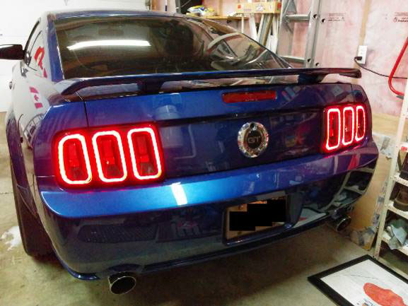
11. Now you’ve completed one side and can easily appreciate the improvement!
12. Complete the same process on the other side and you’ll be done!
Installation Instructions Written By AmericanMuscle Customer Michael Touw 12.21.2013

