 FREE 1 to 3-Day Delivery on Orders $149+ Details
How to install a Roush Front Fascia on your 2010-2012 Mustang
Installation Time
3 hours
Tools Required
- Philips & Straight Screwdriver
- Push Pin Removal tool - Fork
- Ratchet & Extension - 1/4" drive
- 5.5 mm Deep Sockets - 1/4" drive
- 7 mm Deep Sockets - 1/4" drive
- 8 mm Deep Sockets - 1/4" drive
- 10 mm Deep Sockets - 1/4" drive
- 7 mm Wrench
- Pliers
- Flush Cut Side Cutters
- Drill
- Center Punch
- 1/8" Drill Bit
- 3/4" Hole Saw
- 4" Zip-ties or Elec. Tape
- Torque wrench - Lb-in
- Torque wrench - Lb-ft
- Tire removing tools from trunk
- Soft Cloth
- Rubbing Alcohol
- Dupont® 2319 Plastic Prep
- Dupont® 2330S or equivalent Adhesion Promoter (for paint)
- Sand Paper
- Painters Tack Cloth
Installation
Before installing your ROUSH Performance Product(s), read through the entire installation procedure and check to make sure all items are present. Contact ROUSH Customer Service at 1-800-59-ROUSH, 9:00 AM to 5:00 PM EST, weekdays, for any questions regarding fit, missing parts or instructions that are unclear to you.
LIMIT OF LIABILITY STATEMENT
The information contained in this publication was accurate and in effect at the time the publication was approved for printing and is subject to change without notice or liability. ROUSH Performance Products (RPP) reserves the right to revise the information presented herein or to discontinue the production of parts described at any time.
SAFETY REQUIREMENTS
STOP! READ IMPORTANT SAFETY CAUTIONS AND WARNINGS BEFORE PROCEEDING.
IMPORTANT SAFETY NOTICE
Appropriate disassembly, assembly methods and procedures are essential to ensure the personal safety of the individual performing the kit installation. Improper installation due to the failure to correctly follow these instructions could cause personal injury or death. Read each step of the installation manual carefully before starting the actual installation.
1. Always wear safety glasses for eye protection.
2. Place ignition switch in the OFF position.
3. Always apply the parking brake when working on a vehicle.
4. Chock the front and rear tires to prevent unexpected vehicle movement.
5. If working without a lift, always consult vehicle manual for correct lifting specifications.
6. Operate the engine only in well-ventilated areas to avoid exposure to carbon monoxide.
7. Do not smoke or use flammable items near or around the fuel system.
8. Use chemicals and cleaners in well-ventilated areas.
9. Batteries produce explosive gases, which can cause personal injury.
Therefore, do not allow flames, sparks or flammable substances to come near the battery.
10. Keeps hands and any other objects away from the radiator fan blades.
11. Keep yourself and your clothing away from moving parts when the engine is running.
12. Do not wear loose clothing or jewelry that can get caught in rotating parts or scratch surface finishes.
13. Allow the engine, cooling system, brakes and exhaust to cool before working on a vehicle.
WORK SAFELY!
Perform this installation on a good clean level surface for maximum safety and with the engine turned off.
Paint Preparation (Pre-painted parts, skip this section)
1. Using sand paper, remove any plastic flash from the part as required.
2. Wipe each part to be painted with plastic prep (Dupont® 2319 or equivalent).
3. Wipe entire part to be painted with tack cloth.
4. Apply adhesion promoter (Dupont® 23305 or equivalent) prior to color and clear coat applications. This part is made of TPO (Thermoplastic polyolefin) and requires a promoter for paint adhesion.
Stock Fascia Removal
1. Open the vehicle hood and remove eight (8) push pin retainers and the black plastic panel covering the radiator. Refer to Figure 1. Set all parts aside for reinstallation. Note: The push pins are a two (2) part push pin. Remove the center button first to release the barbs and then remove the push pin body.
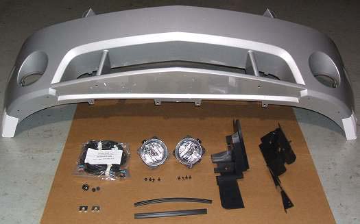
Figure 1
2. Using a 1/4" drive ratchet with a 5.5 mm socket, remove nine (9) screws from the lower close-out panel; one (1) at each wheel well splash shield, four (4) at the front fascia and three (3) at the rear edge of the close-out panel. Refer to Figure 2. Remove the lower close-out panel. Set all parts aside for reinstallation.
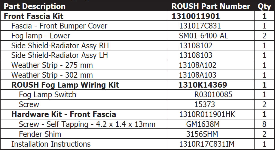
Figure 2
3. Disconnect the left and right side marker lamp connectors. Press the release tab and pull the connector from the side marker lamp. Refer to Figure 3.
(Left side shown, right side similar.)
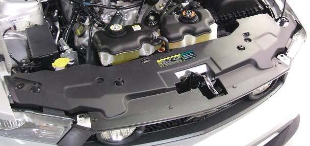
Figure 3
4. Using a forked push pin tool, remove the ambient temperature sensor from the lower left opening of the front fascia. Refer to Figure 4.
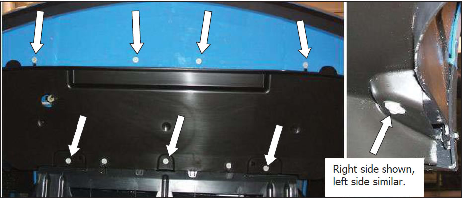
Figure 4
5. Using a 1/4" drive ratchet with an 8 mm socket, remove two (2) screws that attach the top of the fascia to the headlight assemblies. Refer to Figure 5.
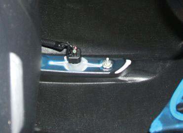
Figure 5 (Left side shown, right side similar.)
6. Lift the two (2) upper fascia mounts from the pins on the head lamp assemblies and slightly pull the upper grille forward to disconnect the left and right fog lamp connectors. Refer to Figure 6. When complete, return the upper fascia mounts to the pins on the head lamp assemblies.
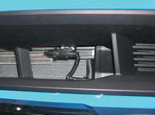
Figure 6 (Left side shown, right side similar.)
7. Using a 7 mm wrench, remove two (2) screws from each wheel well opening. Refer to Figure 7.
(Right side shown, left side similar.) Figure 7
8. With an assistant, lift the two (2) upper fascia mounts from the pins on the headlamp assemblies and remove the front fascia.
ROUSH Fascia Preparation
9. Using a 10 mm deep socket, remove the side markers from the factory fascia by removing two (2) palnuts from each side marker. Transfer each side marker (LH to LH, RH to RH) to the ROUSH Front Fascia. Install two (2) palnuts onto each side marker. Refer to Figure 8.
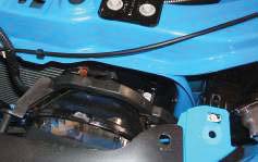
Figure 8
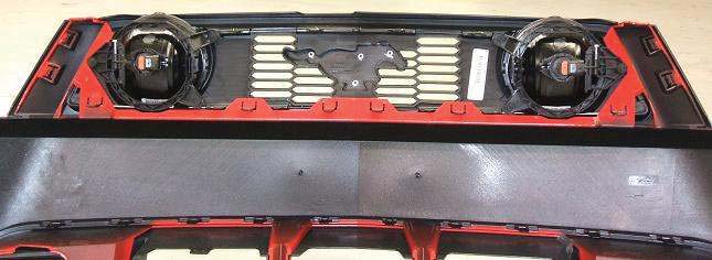
10. Using a 7 mm wrench, install the right Fog Lamp using four (4) supplied screws (two (2) per side). Refer to Figure 10. Note: The Fog Lam ad stment bolt must be on the bottom.
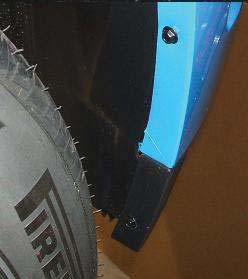
Figure 10
11. Repeat Step 10 for the left Fog Lamp.
12. By hand, disengage ten (10) retainer tabs and remove the upper grille assembly from the factory fascia. Refer to Figure 9. Set aside for reinstallation.
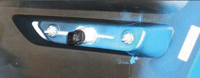
Figure 9
ROUSH Fog Lamp Wiring Harness Installation
13. Disconnect the Negative Battery Cable to prevent electrical accidents.
14. Remove four (4) bolts and the two (2) upper radiator mounting bracket assemblies. Left side shown, right side similar. Refer to Figure 10.
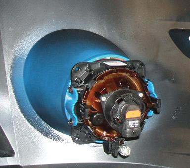
Figure 10
15. Layout the ROUSH wiring harness in the engine compartment according to the following diagram. Refer to Diagram 1.
16. Position the Relay Box onto the drivers side Strut Tower with the top of the mounting brackets in line with the strut tower metal seam. Refer to Figure 11 inset. Mark the two (2) mounting screw locations. Remove the Relay Box and center punch the two (2) mounting locations. Using a 1/8" drill bit and a drill, drill the two (2) holes. Using the two (2) supplied screws, install the Relay Box. Do not over tighten the screws.
17. Route the Fog Lamp section of the wiring harness from the Relay Box, forward, around the air cleaner and along the existing Ford harnesses to the Ford fog lamps. Refer to Figures 12 & 13. Route the left lower fog lamp takeout through the opening under the ABS (Anti-lock Brake System) unit and the right lower fog lamp take out through the opening next to the windshield washer reservoir.
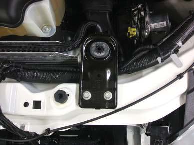
Figure 12
18. Reinstall the two upper radiator mounting bracket assemblies. Refer back to Figure 10. Torque the four (4) bolts to 10 Nm (88 Ib-in).
19. Connect the ground eyelet on the ROUSH Wiring Harness, to the existing Ford ground screw on the passenger side of the radiator core support. Refer to Figure 14. Torque the screw to 10 Nm (89 Ib-in).
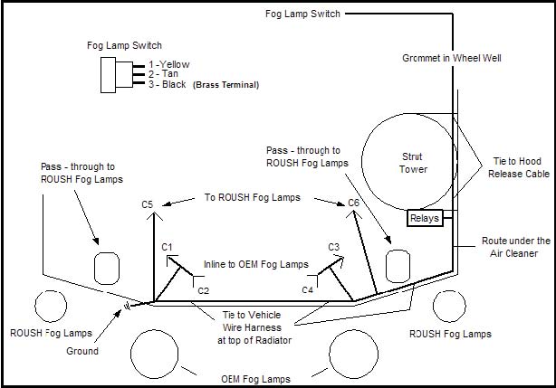
Figure 14
20. Referring back to Diagram 1, connect the ROUSH connectors, C2 and C4, to the factory fog lamp connectors removed from the fog lamps in Step 6.
21. Zip-tie or tape the ROUSH Wiring Harness to the Ford wiring harnesses at various location to secure the harness and eliminate chafing.
22. Remove the driver's side front wheel.
23. Remove two (2) screws and nine (9) push pin retainers and the left front inner wheel well liners. Refer to Figure 15.
Note: There are two different type push pins used. One type is a two piece push pin which requires a phillips screw driver to remove the center pin, and then the push pin body can be removed. The second type is also a two piece push pin which requires a push pin tool to pry out the center pin and then the push pin body can be removed.
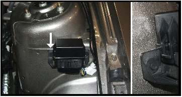
Figure 15
24. Route the Fog Lamp Switch section of the ROUSH Wiring Harness along the hood release cable in the engine compartment and pass through an existing hole into the wheel well. Refer to Figure 16.
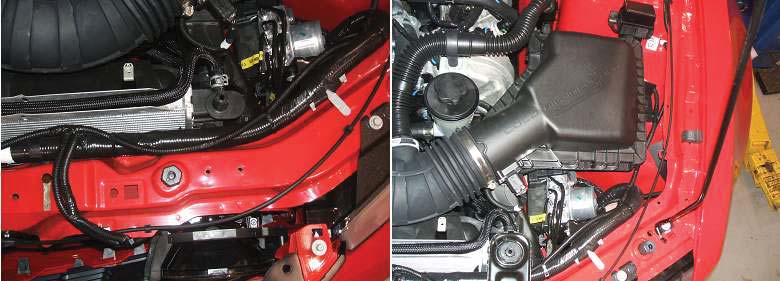
Figure 16
25. Use side cutter pliers to cut the end off the spare nipple on the wiring harness grommet located at the rear of the wheel well. Insert the ROUSH Wiring Harness, with the 3 terminals, through the hole in the grommet. Place a zip-tie or tape around the nipple to hold the ROUSH Wiring Harness in place and seal the grommet. Refer to Figure 17. Note: This grommet has a foam honeycomb backing. Remove material as required to pass the wiring harness through the grommet.
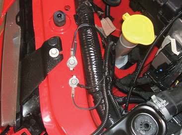
Figure 17
26. Re-install the driver's side front wheel well liners with the nine (9) push pin retainers and two (2) screws that were removed in Step 23. Refer back to Figure 15. Insert the body of the push pin first and then press in the center button.
27. Reinstall the left front wheel. Torque the wheel lug nuts to 133 Nm (98 Ib-ft).
28. Open the driver's door. Remove two (2) screws from the bottom edge of the lower steering column cover. Grasp the cover from under the steering column and pull the cover down just enough to disengage the three (3) spring retainer clips. Swing the right side of the lower steering column cover toward the driver's door to remove the tab from behind the left foot well panel. Refer to Figure 18 and inset.
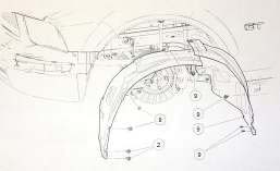
Figure 18
29. Measure, mark and drill a 9/32" pilot hole into the front face of the steering column lower cover. The center of the hole must be located 3" down from the top edge and 3" from left side of the lower cover. Using a 3/4" hole saw, drill a 3/4" hole through the steering column lower cover at the pilot hole. Refer to Figure 19.
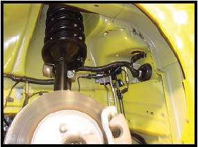
Figure 19
30. Remove the jam nut from the ROUSH Fog Lamp Switch. Turn the panel over and using flush cut side cutter pliers and the jam nut as a reference, remove portions of the ribbing from around the hole to allow space for the switch jam nut. Debur the hole and install the ROUSH Fog Lamp Switch and jam nut. The switch must be installed with the brass colored terminal to the bottom of the panel. Refer to Figure 20.
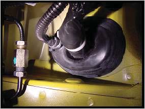
Figure 20
31. Route the ROUSH Fog Lamp Harness through the opening in the lower dash. Refer to Figure 21.
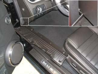
Figure 21
32. Return the steering column lower cover to the vehicle. Referring back to Diagram 1, on Page 10, connect the three (3) wiring terminals to the Fog Lamp Switch. Reinstall the steering column lower cover by reversing the removal procedure. Refer back to Step 28. Ensure that the wire harness is not trapped between the lower cover and the dash structure. Refer to Figure 22.
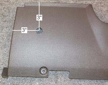
Figure 22
33. Use Zip-ties or tape to secure any excess wiring under the dash.
Radiator Side Shields
34. Install the LH (12" (302 mm)) Weather Strip onto the LH Radiator Side Shield (13108103) and the RH (10 3/4" (275 mm)) Weather Strip onto the RH Radiator Side Shield (13108102) as shown in Figure 23. Ensure the Weather Strip is fully pressed on and the lip of the Weather Strip is positioned as shown in Figure 23 inset.
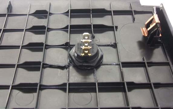
Figure 23
35. Using a forked push pin tool, remove two (2) push pins and the RH radiator side shield. Save the push pins for reuse.
36. Install the new RH Radiator Side Shield. Secure the shield to the chassis using the take off push pins. Ensure that the fog lamp harness is returned to its original position. Refer to Figure 24.
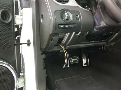
Figure 24.
37. Using a forked push pin tool, remove the Ambient Temp Sensor wire harness retainer from the mounting hole on the backside of the LH side shield. Refer to Figure 25.
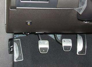
Figure 25
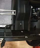
38. Remove two (2) push pins from the LH radiator side shield. Save the push pins for reuse. Disengage the four (4) tabs located inside the air inlet opening to separate the side shield from the air cleaner inlet tube assembly. Refer to Figure 26. Remove the LH radiator side shield.
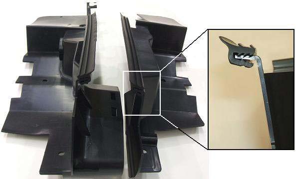
Figure 26.
39. Install the new LH Radiator Side Shield by reversing the removal process. Align the air inlet openings and snap the four (4) tabs into the slots. Secure the shield to the chassis using the take off push pins.
40. Install the Ambient Temp Sensor and wire harness retainer to the holes in the lower portion of the LH Radiator Side Shield as shown in Figure 27.
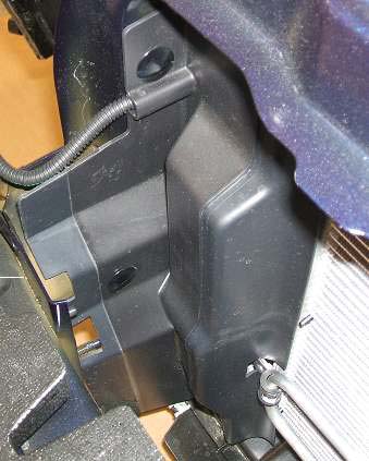
Figure 27
ROUSH Front Fascia Installation
Assembly Note: Due to variation in the Mustang body, shims may be required to expand the fender to fender width for an improved fit of the ROUSH Fascia.
41. Install the ROUSH Front Fascia. Hook the upper fascia mounts onto the pins of the head light brackets. Reinstall the two (2) bolts to the head light brackets. Refer back to Figure 5. Check the fit of the ROUSH Fascia to the fenders. If the Front Fascia is wider than the fenders, shims are required. Refer to Figure 28.
42. If shims are required, remove the two (2) bolts from the head light brackets and remove the Front Fascia.
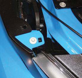
43. Using a ratchet and 10mm socket, remove the two (2) bolts shown in Figure 29.
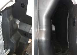
Figure 29
44. Pull the corner mounting bracket outward and insert one (1) shim as shown. Refer to Figure 30. Reinstall the two (2) bolts. Torque the shim bolt to 8 Nm (71 Ib-in). Tighten the corned bracket bolt taking care not to strip out the plastic press nut.
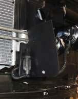
Figure 30
45. Reinstall the ROUSH Front Fascia. Hook the upper fascia mounts onto the pins of the head light brackets. Reinstall the two (2) bolts, removed in Step 5, to the head light brackets. Refer back to Figure 5. Torque the bolts to 8 Nm (71 Ib-in).
46. Reinstall two (2) screws, removed in Step 7, to each wheel well (4 total). Referback to Figure 7.
47. Install the upper grille assembly onto the ROUSH Front Fascia. Referring back to Diagram 1, connect connectors C1 & C3 to the upper fog lamps. Align the ten (10) tabs on the grill assembly to the slots on the Front Fascia. Press the grille assembly into place. Refer to Figure 31. Ensure all ten (10) retainer tabs are fully inserted into there respective slots.
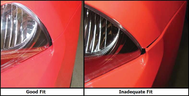
Figure 31
48. Reinstall the upper radiator cover and eight (8) push pins removed in Step 1. Refer back to Figure 1. Insert the push pin body into the hole and then the push pin button.
49. Reconnect the left and right side marker connectors. Refer back to Step 3 and Figure 3. Ensure the connectors are fully inserted and snap into place.
50. Referring back to Diagram 1, connect the ROUSH Fog Lamp Wiring connectors, C5 and C6, into the ROUSH Fog Lamps. Ensure the connectors are fully inserted and snap into place.
51. Reinstall the lower close-out panel using the nine (9) screws removed in Step 2. Refer back to Figure 2.
ROUSH Fog Lamp Functional Test
52. Reconnect the Negative Battery Cable.
53. Turn the ignition switch to the ON position.
54. Turn the head lamp switch clockwise so that the headlamps are ON and ensure the headlamps are in the Low Beam setting. (Note: Fog lamps will not operate with the headlamps in the High Beam setting.) Pull out the switch to turn ON the Ford set of fog lamps. The ROUSH Fog Lamp Switch LED Indicator should be OFF, and the Ford fog lamps should be ON.
55. Toggle the ROUSH Fog Lamp Switch to the ON position. The LED Indicator on the ROUSH Fog Lamp Switch should turn ON, the Ford fog lamps should turn OFF and the ROUSH Fog Lamps should turn ON.
Congratulations. You have completed the installation of the ROUSH Performance Products, Front Fascia Kit. It is recommended you save all parts removed from your vehicle during the installation of this kit.
