 FREE 1 to 3-Day Delivery on Orders $149+ Details
How to Install Raxiom Fog Light Switch and wiring kits on your Mustang
Installation Time
2 hours
Tools Required
- Flat head & Phillips screwdriver
- Ratchet & Socket set
- Adjustable Wrench
- Wire stripping tool or razor blade

Shop Parts in this Guide
Parts List:
LED Fog Lights/ Bezels
(if you ordered part#394020)
Wiring harness
Ford OEM Switch
Parts Bag
Please familiarize yourself with the parts included as well as the instructions before attempting installation. Please seek the help of a certified technician if you feel unable to complete the installation safely and properly. Failure to read and follow the instructions below may result in personal injury or damage to property. Raxiom assumes no liability for failures to comply with guidelines and warnings outlined in this instruction manual.
If you are receiving this instruction manual with part #394021 (Raxiom Fog Light Wiring & Switch Kit), skip to the 'Wiring in Engine Bay' section on page 2. Otherwise, begin steps immediately below.
Fog light installation into bumper:
Removing the bumper is not necessary. Driving the vehicle onto ramps or raising the front end of the car will greatly ease installation. Before beginning the steps below, turn off the car, remove key, and engage the emergency brake.
1. Open hood of car and make sure hood is held open securely.
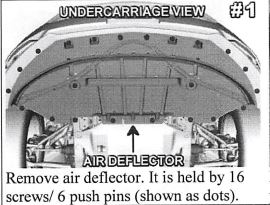
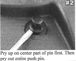
2. Removing the air deflector will allow you access to fog light mounting points. The air deflector is held on by 16 screws and 6 push pins (shown as dots in picture 1 below). Use a ratchet & 7mm socket OR wrench to remove the screws. The pins are removed with a flat head screwdriver - pry up on center part of the pin and then pry up on the body of the pin. See picture 2. The deflector is removed by pulling back/ down gently. Set aside hardware and deflector for re-attachment later.
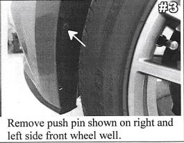
3. Use flathead screwdriver to remove the push pin shown in picture 3 on each front wheel well. This push pin helps hold on the left and right side bezel. Save for re-installation later.
4. Un•lu turn si .1 connectors on each side. You will reuse your existin: turn signal lams.
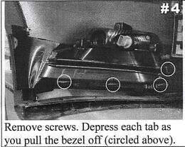
5. Remove bezel inserts currently in bumper. Bezels will be removed from behind the bumper. 6 - 7mm screws hold the bezel in place — 4 surrounding the opening in the bumper, and 2 near the edge of the wheel well liner. Once you have removed these, 4 body-colored tabs hold on each bezel (see picture 4). Each tab must be depressed one at a time as you begin to pull the bezel off. It is usually best to start at the outer side and work your way inward. All screws will be re-used on new fog light bezel.
6. Remove the turn signal lamps from each bezel. Each lamp is held on by 3 — 7mm screws. Re-use screws to install the lamps in the new bezels that came pre-assembled in the fog light kit. Now fog lights/ bezels will be installed. Each fog light comes pre-installed onto the back of the new bezel, no additional assembly is required.
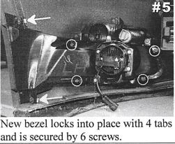
7. Install new parts. Each bezel needs to snap onto all 4 of the body colored mounting tabs. See picture 5 below.
8. Use the 6 screws removed earlier to secure each bezel to the bumper. Take note: The 2 screws (see arrows in picture 5) with a large washer can only be re-installed near the wheel well liner which secures the outer edge of the bezel. Do not use these screws around the bezel opening. All screws can be tightened with a ratchet and 7mm socket. Do not over-tighten screws. See picture 5 below.
Wiring in Engine Bay:
1. Remove the battery cover on the passenger side. It is held on by 3 caps that you can unscrew by hand. Lift cover off and save for re-attachment later.
2. Disconnect negative (black) battery cable from the car battery. This is done by loosening the bolt located on the side of the battery cable terminal with a 10mm socket or wrench. You may let the cable sit off to the side. Make sure the cable has been disconnected! Do NOT allow it to make contact with the 12v Red battery cable!
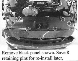
3. Remove the black panel which covers the radiator shown in picture 6. The panel is attached by 8 push pins. See picture 2. Save pins and black panel for re-installation later.
4. Locate the fuse box. It is located behind the passenger side head light. Open the access cover.
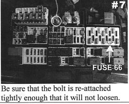
5. Connect the orange wire to the 12 volt power cable entering the fuse box circled in picture 7. A 10mm socket or wrench can be used to remove the nut holding the power supply cable. A ring terminal is located at end of the orange wire which will slide over the post. Re-attach nut tightly. While tightening be careful not to allow your wrench or ratchet to come in contact with any other metal object such as the car body.
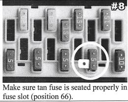
6. A fuse tap is included in the parts bag. It comes pre-installed on a 5 amp tan mini-fuse to ease installation. Remove the existing fuse from position 66 in your fuse box. Refer to pictures 7 / 8 / 9 or the underside of the fuse box access cover for proper fuse location. It is critical that you connect to the proper fuse.
7. Install the replacement mini-fuse/ fuse tap.
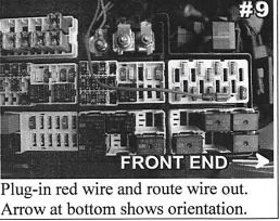
8. Plug short red wire coming from wiring harness into the fuse tap you just installed. Route the red wire out of the fuse box as shown in picture 9 below.
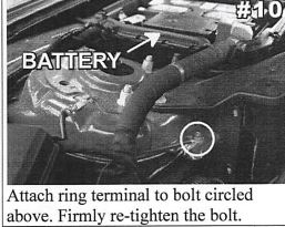
9. Use an 8mm socket or wrench to attach the black ground cable ring terminal to the bolt shown in picture 10. Re-attach the bolt so the ring terminal makes ro er contact and the bolt is tight.
10. Route the wiring for the driver side fog light/ switch over the radiator along the frame of the car.
11. Drop the wiring for each light down to the fog light locations. Route wiring for the passenger compartment (green wire) along the driver's side fender towards passenger compartment
12. Plug the fog light connectors into the fog lights.
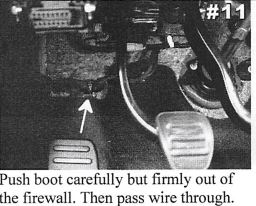
13. Open the drivers' side door and locate rubber boot to the left of the pedals. It is hidden behind an insulation pad. Carefully push to remove from the firewall. See picture 11. This is where we want to route the green wire into the passenger compartment.
14. The easiest way to do so is to route the wiring down past the brake booster toward the ground. Follow the existing bundle of wiring. Tip: Shine a flash light through the hole in the passenger compartment — this will assist you in feeding the wires down to the proper opening/ area.
15. While inside the passenger compartment, pull the switch wiring through the firewall.
16. Re-install rubber boot in the firewall by gently pulling it back into the hole. This will be a little bit more difficult with the additional wiring running through. Make sure it seals well. If you find this difficult, you can optionally cut a hole in the rubber boot and feed the wire through that way. Just be sure you don't damage the wiring bundle that runs through the center of the rubber boot.
Installing switch in passenger compartment:
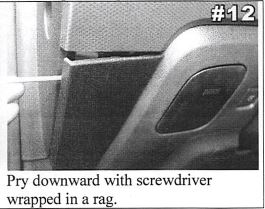
1. Use a flat head screw driver wrapped in a rag to carefully remove the panel below the switch anel. This will hel allow switch removal. See s icture 12. 3 cli s s hold the panel in place.
2. You will notice that at the bottom left corner of the switch panel there is a tab with a screw at the end. The screw will need to be removed with a 7mm socket or adjustable wrench. Save for re-attachment later.
3. Very carefully remove the switch panel. Start loosening the panel at the bottom left and work your way up — do your best to pull straight out. The switch panel is held on with 4 clips. These will make a 'popping sound' when they unclip — this is normal.
4. Unplug the head light switch panel and remove from vehicle.
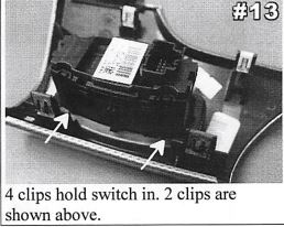
5. The head light switch is removed from the switch panel by depressing 4 tabs around the base of the switch. The switch will then come out of the switch panel. See picture 13 above.
6. Install the new switch into the switch panel. It should snap into place with very little force.
7. Felt electrical tape is wrapped around the bundle of wires that plugs into the switch. Carefully pull back the tape several inches so you have better access to individual wires.
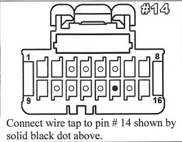
At this point we will connect the green wire from the fog light wiring harness to the correct wire behind the headlight switch connector. Take a look at the back of the headlight switch connector (where the wires enter — also called the wire end). You'll notice that on each corner of the connector there is a number which designates the number of each wire. The top row is for pin numbers 1 through 8, the bottom row is for pin numbers 9 through 16. See picture 14 which illustrates the wire end of the connector.
8. Locate pin #14 which is a solid gray wire. See picture 14 for the proper location of the wire. BEWARE — there is another gray wire in the wire bundle. Be sure you have the correct wire.
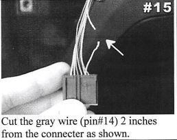
9. Carefully cut the wire 2 inches from the switch connector. Before cutting, double check to make sure you are cutting the correct wire. This step is necessary for the fog lights to function properly. See picture 15.
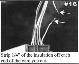
10. Now, strip 1/4" of insulation from the gray wire. You can do this with a wire stripping tool, or very carefully remove the insulation with a razor blade. If you use a razor blade, be careful not to cut through the copper wire. See picture 16.
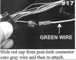
11. Locate the Posi-lock connector on the end of the green wire. It is red in color. Unscrew end cap.
12. Slide the red end cap onto the gray wire that runs into the headlight switch connector. Now carefully screw the red posi-lock connector back onto the red cap. Give it a gentle tug to make sure it is secure. See picture 17 & 18.
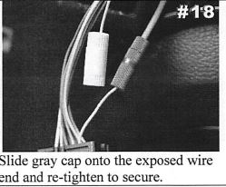
13. Locate the gray wire cap in the parts bag. Unscrew the cap.
14. Slide the other end of the gray wire you cut into the cap and screw cap closed. Give it a gentle tug to make sure it is secure. This will properly cover the exposed end without the need for electrical tape. See picture 18.
15. Plug head lamp switch wiring into your new OEM head lamp switch.
16. Re-install the head lamp switch panel into the dash.
Final Installation:
1. Re-connect the negative battery cable to the car battery. Remember to re-tighten the bolt.
2. Double check everything to make sure it was connected properly. Now press the Engine Start button. Test the fog light switch to make sure the lights turn ON and OFF. If the lights do not power on or do not turn off with the switch, visit the trouble shooting section below. Otherwise proceed to the next step.
3. Using the supplied zip ties, secure the wiring in the engine bay and passenger compartment. Be sure to securely zip tie any components that may rattle such as the relays next to the fuse box.
4. Be sure you secure all wiring under the dash and near the pedals. Failure to do so could cause damage to the wiring or cause an accident.
5. Adjust the lights. This is best done at night or in a dark garage. Turn the lights on and position the car about 15 feet from the wall. On each fog light the Philips screw can be turned left or right to adjust up and down. Adjust the lights so that the individual light patterns are level on the wall.
6. Re-install the dash panel, air deflector and radiator cover.
7. Enjoy your new fog lights! The fog lights can be operated anytime the vehicle is ON. You may operate the fog lights as daytime running lights by turning them on while in the auto headlamps position. Your fog lights will turn off automatically when the vehicle is turned OFF. There is no interior indicator light to show fog light status.
