FREE 1 to 3-Day Delivery on Orders $149+ Details
How to Install Roush R2300 550HP Supercharger - Phase 2 Kit on your Mustang
Installation Time
1 days
Tools Required
- 1/4” and 3/8” Drive Ratchets with Extensions
- Metric and Standard Socket Sets (short and deep recommended)
- 1/2” Drive Ratchet or Breaker Bar
- Metric and Standard Wrench Sets
- 3/8” Drive Torque Wrench (7-35 ft-lb range)
- Short Phillips-head Screwdriver
- Hex Key Set
- Teflon pipe sealing tape or equivalent
- 5/8” Fuel Line Removal Tool
- T-20 Torx Bit Screwdriver or Socket
- Soldering Iron and Solder
- Wire Strippers
- Wire Crimpers “W” type for OEM-style wiring connectors
- 1/8”, 9/64”, and ¼” Drill Bits and Drill motor
- Coolant (meeting G-05 specification)
- 6” Scale, Tape Measure, or Other Measuring Device
- Brake Parts Cleaner
- Assembly Lubricant (White Lithium Grease or Petroleum Jelly)
- Electrical Tape
- Sharp Knife or Razor Blade
- Tie Straps (Zip Ties)
- Trim Pad Tool (for pushpin removal)
- Fender Cover (2)
- Medium Strength Thread Locker – Loctite 242 (blue) or equivalent

Shop Parts in this Guide
Installation Instructions
SECTION A - DISASSEMBLY
The following section will guide you through the disassembly of the stock components. Special care should be taken to label fasteners and parts that are taken off during this procedure since many will be reused:
1. Cover both fenders with fender covers to protect the vehicle finish.
2. Release the fuel system pressure (NOTE: The following procedure is taken directly from the Ford Service Manual, section 310-00).
WARNING: Fuel in the fuel system remains under high pressure even when the engine is not running. Before working on or disconnecting any of the fuel lines or fuel system components, the fuel system pressure must be relieved. Failure to do so can result in personal injury.
WARNING: Do not smoke or carry lighted tobacco or open flame of any type when working on or near any fuel-related components. Highly flammable mixtures are always present and can be ignited, resulting in personal injury.
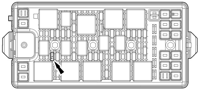
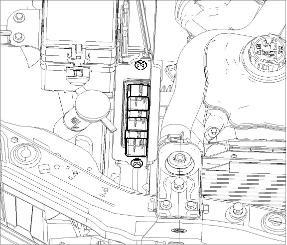
a. Remove the fuel pump module fuse. NOTE: The fuel pump module fuse is located in the bussed electrical center, location F41.
b. Start the engine and allow it to idle until it stalls.
c. After the engine stalls, crank the engine for approximately 10 seconds to make sure the fuel injector supply manifold pressure has been released.
d. Turn the ignition switch to the OFF position.
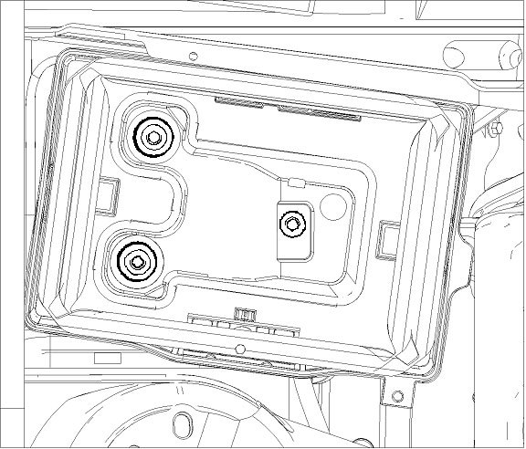
3. Using an 8mm wrench, disconnect the (-) negative & ( ) positive connections to the battery. Remove the battery hold down bolt using an 8mm socket wrench. Remove the hold down & battery. With an 8mm socket wrench, remove the 3 bolts holding the battery tray to the vehicle. Remove the battery tray.
Before continuing, refer to the CALKIT included with your ROUSHcharger kit. Determine the PCM flash method you will be using. If performing the PCM flash yourself or at a preferred ROUSH dealer, proceed to step 5. If sending the PCM to ROUSH for a ROUSH performed PCM flash, continue with step 4.
4. Disconnect the 3 PCM (Powertrain Control Module) connectors by lifting the grey levers over the connector back shell and lifting the connectors from their sockets. Remove the PCM by removing two 10mm bolts and pulling the PCM forward and lifting out of the engine compartment. Follow the instructions on the next page as soon as possible to help minimize the amount of time you are without a PCM.
Important: Be sure to write your VIN number and phone number (in case we need to contact you for additional vehicle information) on the PCM using a permanent marker.
INSTRUCTIONS FOR RETURNING THE PCM TO ROUSH FOR CALIBRATION
Outlined below are the instructions for returning your stock powertrain control module (PCM) to Roush Performance Products so we can install our calibration to make the engine run properly with the new components. Please complete the “Optional Roush PCM Flash” request document and include it, along with the PCM, and the “Voucher Card”. Once we receive your PCM, we will reprogram and return it back to you the same day for next-day delivery. Operating your engine without our calibration will result in engine damage or failure and will void all warranty.
Note: It is important to reinstall the PCM in the vehicle it came from to prevent setting a trouble code and having to relearn the anti-theft code which can only be performed using specialized Ford Service Bay tools.
- If you haven’t already done so, write your vehicle identification number (VIN) and phone number on the PCM using a permanent marker.
- Using bubble wrap, or another appropriate packing material, wrap and package the PCM to help prevent it from being damaged during shipping.
- Place the wrapped PCM in an appropriate shipping box.
- Complete the “Optional ROUSH PCM Flash” request document (PCM-FLASHDOC) and attach the flash “Voucher Card” (P1305-P1CALKIT/P1305-P2CALKIT) to the document.
- Include the “Optional ROUSH PCM Flash” document and the “Voucher Card” in the shipping box, along with the PCM.
- Ship the PCM and contents to:
ATTN: PCM FLASH
39555 Schoolcraft Rd
Plymouth, MI 48170
Upon receipt of the PCM, a customer service representative will contact you to arrange payment. Once you receive your ROUSH flashed PCM, reverse step 4 for PCM installation.
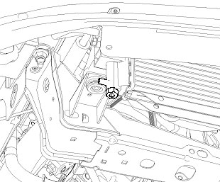
5. With the engine cool, remove the cap on the engine coolant degas bottle and drain the coolant using the petcock located on the lower passenger side of the radiator.
TIP: Connect 3/8” hose to the drain fitting next to the petcock and run into a clean drain pan or bottle. Use a ¾” wrench to open petcock and allow coolant to drain out of the fitting.
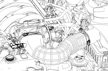
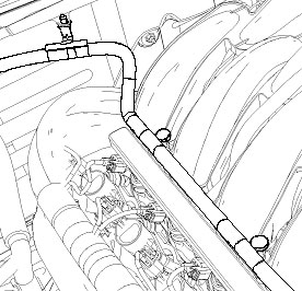
6. Disconnect the PCV vent tube from the right-hand cam cover and clean air tube. Using an 8mm nut driver, loosen the 2 clamps at either end of the clean air tube. Remove the clean air tube from the throttle body and airbox.
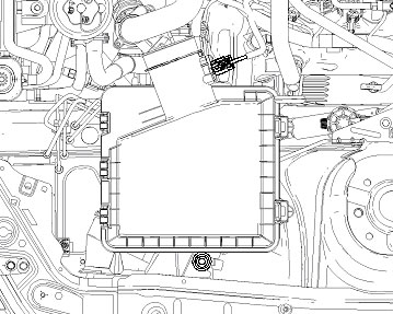
7. Remove the MAF (mass air flow) connector by pulling the red locking tab back and pressing the black release tab. With a 10mm socket wrench, remove the airbox hold down bolt. Firmly grasp the airbox and pull up to remove it from the vehicle.
8. Disconnect ETC (electronic throttle control) & TPS (throttle position sensor) connectors from the throttle body (Pull the red locking tab back; press the black release tab to disengage the lock).
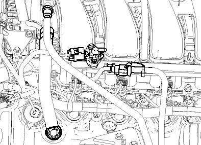
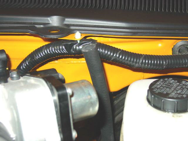
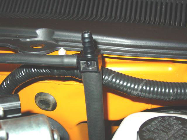
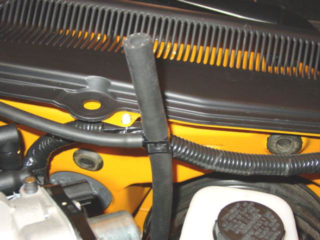
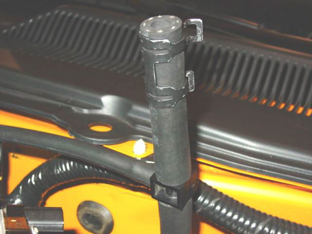
9. Remove the PCV line from the intake manifold and left-hand cam cover. Remove the VMV line from the intake manifold and position out of the way. Remove the vacuum line and electrical connector from the IPTS on the fuel rail and save for reuse. Remove the black safety clip from the fuel line connection. Place rags under the fuel rail, using a 5/8” fuel line tool (wrap additional rags around the tool) disconnect the fuel line from the fuel rail.
10. Disconnect the alternator harness from the positive battery terminal and remove the harness clips from the fuel rail studs.

11. Disconnect the wiring connectors from the fuel injectors (8). Remove the four 8mm stud bolts holding the fuel rail to the intake manifold and remove the fuel rail assembly with injectors. There may be some additional fuel leakage around the injectors. Clean all excess fuel before proceeding.
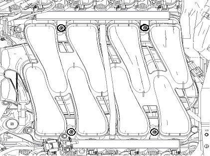
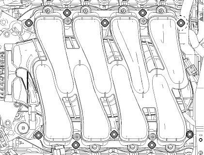
12. Disconnect the CMCV connector located in the center rear of the intake manifold. Remove the brake booster vacuum line from the intake manifold. Pull the wiring harness off of the stud bolt on the driver side rear of intake manifold. Remove the ten fasteners which used to bolt the intake manifold to the cylinder heads. Save the rear stud for reuse. Remove the intake manifold. Use tape or equivalent to cover the cylinder head ports to prevent engine contamination.
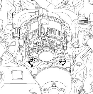
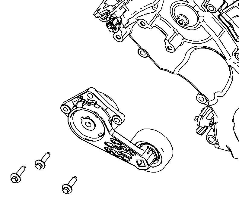
13. Release the accessory drive belt by rotating the tensioner clockwise with a ½“ breaker bar or ratchet and slip the belt off the water pump pulley and remove the belt. Disconnect the regulator connector and the battery cable from the alternator. Using a 10mm socket wrench, remove the four upper support bracket bolts. Remove the two 15mm alternator nuts and remove the alternator.

14. 2005 – 06 VEHICLES ONLY - Remove the upper radiator and bypass circuit hoses. Remove the clamps from the upper radiator hose and save for later use. On the back side of the water crossover, disconnect the heater hose. Remove the water crossover using a 10mm socket wrench.
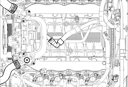
14. 2007 – 09 VEHICLES ONLY - Remove the upper radiator hose. On the back side of the water crossover, disconnect the heater hose. Remove the water crossover using a 10mm socket wrench.
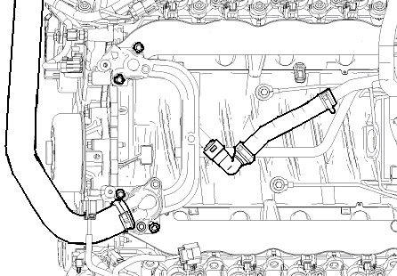
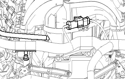
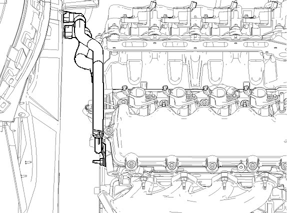
15. Disconnect the rubber portion of the heater hoses from the metal tubes at the rear of the righthand cylinder head. Remove the heater tube assembly from the engine by removing the stud on the back side of the passenger cylinder head and sliding off the water pump fitting in the block.
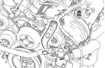
16. 2005 – 06 VEHICLES ONLY - Locate the coolant hose hanger on the front of the engine and remove.
17. Remove the tensioner and retain the bolts for reuse later.
SECTION B - MODIFICATIONS
The following section will guide you through the required modifications of existing components and build up of the assemblies used to complete the installation. With the exception of the intercooler pump bracket mounting, all of this work can be performed away from the vehicle.
Alternator Modification
In order for the alternator to be installed in its new location, two of the original mounting ears must be removed. Using a band saw or similar cutting tool, remove the mounting ears shown. Be careful to avoid getting debris inside of the alternator when removing these features.
2005-08 Alternators should look similar to the pictures below:
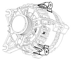
BEFORE
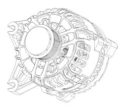
AFTER
2009 Alternators should look similar to the pictures below once mounting ears have been removed:
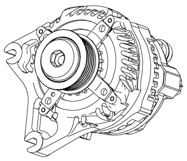
BEFORE
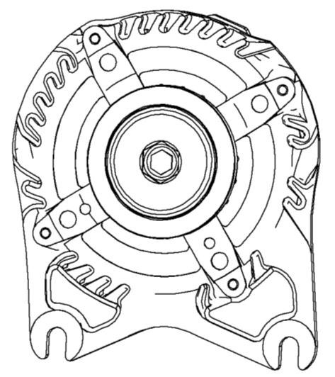
AFTER
VMV Modification
1. Remove split loom convolute from stock VMV hose assembly.
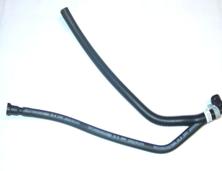
2. Mark hose at 130mm (~5.25in) from end of straight connector.
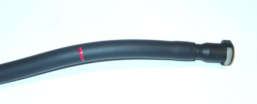
3. Using a knife, cut the hose at the applied mark
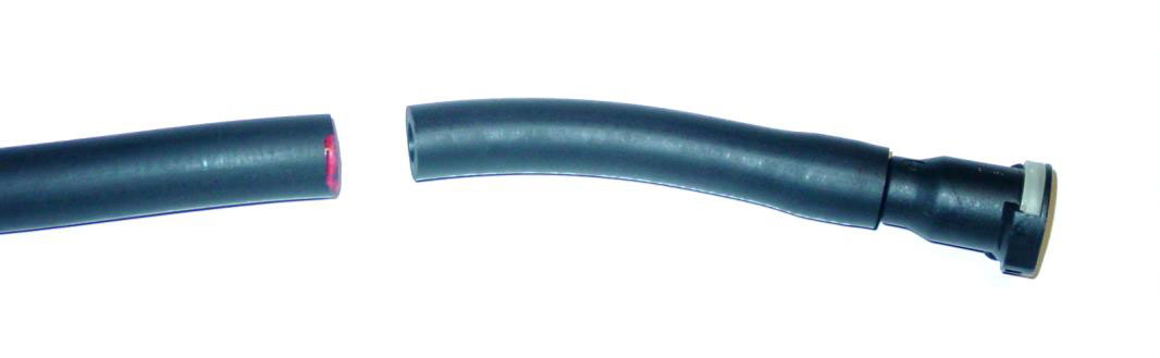
4. Using a knife, cut the hose as shown to remove the straight connector from the cut off piece of VMV hose.
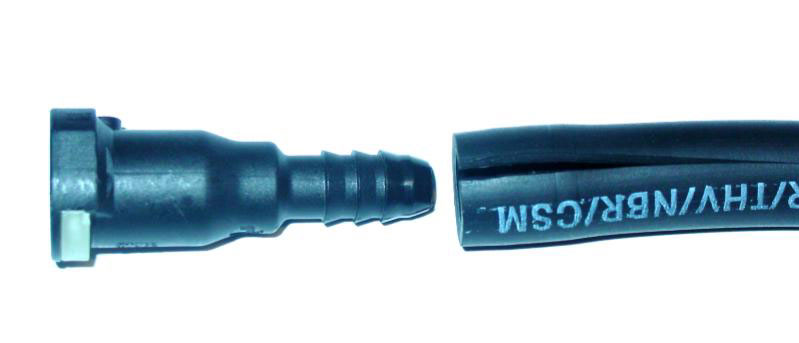
5. Re-install straight connector into shortened VMV hose.
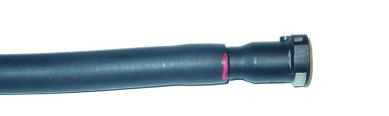
6. Using a knife, cut off 100mm (~4 in) of split loom convolute to fit the shortened VMV line. Reinstall the split loom convolute onto the modified VMV hose.

Brake Booster Hose Modification
Note: This modification does not require removal of the hose from the booster. Removing the hose from the booster could damage the booster fitting.
1. Remove the split loom convolute from brake booster hose. Remove the T-fitting with the 7/32” vacuum hose and the short hose from the brake booster hose assembly.
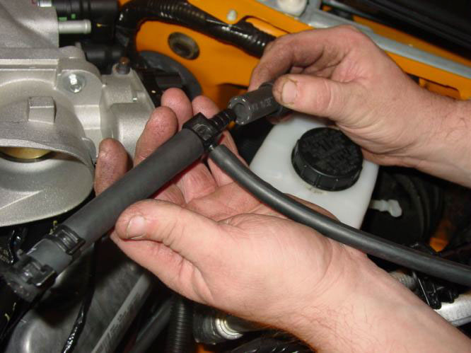
2. Remove and keep T-fitting with the 7/32” vacuum hose and hose clamp from the take off brake booster hose. Discard short section of the brake booster hose.
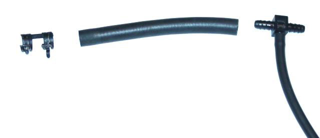
Discard center piece
3. Remove and discard the 7/32” vacuum hose retaining clip. Measure and mark 45mm from the end of the 7/32” vacuum hose. Use a knife to cut the vacuum hose at mark.
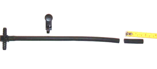
Discard upper clip and short cut piece on right
4. Mark the brake booster hose 80mm from end. Using a knife, cut the brake booster hose at the applied mark.
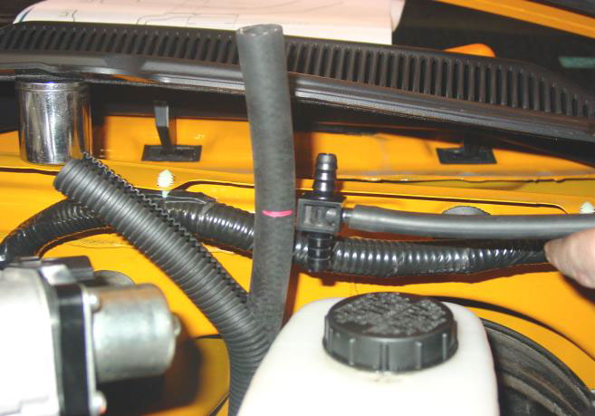
5. Re-install T-fitting with the 7/32 vacuum hose onto the cut brake booster hose.
6. Install the 80mm piece of hose, which was cut off in step 3, on the open end of T-fitting.
7. Install the hose clamp onto the end of the 80mm hose
Heater Tube Assembly Modification
1. The upper tube and hose on the heater tube assembly is not used (a new tube is supplied in the kit). Using a die grinder or air saw, cut the forward bracket that connect the two tubes together and cut along side of the rear bracket through the upper tube. De-burr all sharp edges. Retain the lower tube which connects to the water pump and the mounting bracket for reinstallation.
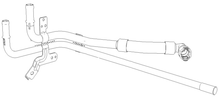
Discard upper tube, keep lower tube
Wiring Harness Modifications
The following details the modifications to the factory engine harness which are necessary to complete the installation of this kit. These modifications should be done without removing the harness from the engine as it will be easier to verify final locations of the break out points. Extreme care must be taken to insure that wiring and/or its insulation is not accidentally damaged while removing the convoluted tubing. All of the convoluted tubing and various clips that are removed while making these changes are intended to be reinstalled in the same place unless otherwise noted.
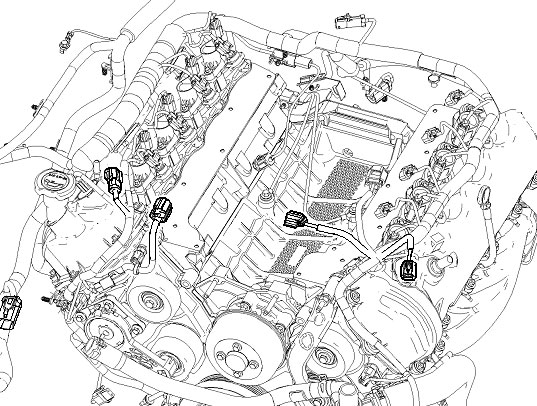
Connectors for Wiring Circuits that will need to be modified
1. Make a note of the locations of the harness retaining clips and breakout points. With the harness still fastened to the engine with the factory retainers, carefully cut the tape off of the convoluted tubing and wiring harness on the drivers side of the engine (where the ETC branches out of the main harness) using a razor or utility knife. The area is highlighted in the following diagram. The convoluted tubing is split from the factory so follow the split. Lift the wiring out of the convoluted tubing without disturbing the factory retainers wherever possible. Expose all of the internal wiring from the MAF/ETC split all the way around to the rear of the driver side cam cover.
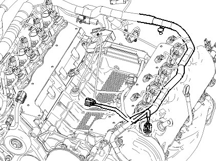
Pull wiring out from this section.
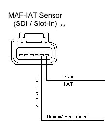
2. Locate the 6-wire MAF sensor connector. Looking into the face of the connector with the release tab positioned up, the first two wires in the connector (IAT) from the right are grey and grey w/ red tracer. Cut both of these wires approximately 5 to 6 inches from the back of the connector.