 FREE 1 to 3-Day Delivery on Orders $149+ Details
How to Install Roush Hood Scoop - Unpainted on your 2013 Ford Mustang
2013 Mustang Hood Scoop
P/N: 421395 (R1313-16C630)
Application: 2013 Ford Mustang
2013 Mustang 5.0L with Automatic/Manual Transmission
2013 Mustang 3.7L with Automatic/Manual Transmission
Installation Instructions
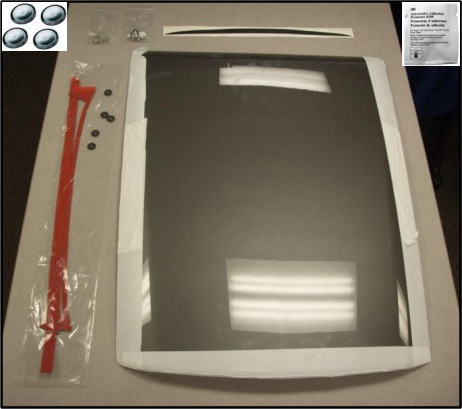
Before installing your ROUSH Performance Product(s), read through the entire installation procedure and check to make sure all items are present. Contact ROUSH Customer Service at 1-800-59-ROUSH, weekdays from 9:00 AM to 5:00 PM EST, with any questions regarding fit, missing parts or instructions that are unclear to you.
| Description | Part Number | Qty |
|---|---|---|
| Hood Scoop | 1313-16C630 | 1 |
| Tape Kit | 1313-16C630TAPE | 1 |
| Nuts, M6 x 1.00 | W704521 | 8 |
| 7/8" ID Flush Plug, Black | 9750K25 | 4 |
| Adhesion Promoter | 021200-27571 | 1 |
| Hood Scoop Inlet Graphic | 1313-16C630GFX | 1 |
| Template | 1313-16C630TMPL | 1 |
| Installation Instructions | 1313-16C630IM | 1 |
EQUIPMENT AND SUPPLIES REQUIRED
Electric or Pneumatic Drill
Drill Bit Set
10MM Metric Socket (Deep Recommended)
Isopropyl Alcohol and Terry Cloth
Safety Glasses
Ratchet
Torque Wrench
Trim Tool (Hood Liner Removal)
Commercially Available Clear Coat
Blanket
7/8” Hole Saw
LIMIT OF LIABILITY STATEMENT
The information contained in this publication was accurate and in effect at the time the publication was approved for printing and is subject to change without notice or liability. ROUSH Performance Products (RPP) reserves the right to revise the information presented herein or to discontinue the production of parts described at any time.
SAFETY REQUIREMENTS
STOP! READ IMPORTANT SAFETY CAUTIONS AND WARNINGS BEFORE PROCEEDING.
IMPORTANT SAFETY NOTICE
Appropriate disassembly, assembly methods and procedures are essential to ensure the personal safety of the individual performing the kit installation. Improper installation due to the failure to correctly follow these instructions could cause personal injury or death. Read each step of the installation manual carefully before starting the actual installation.
1. Always wear safety glasses for eye protection.
2. Place ignition switch in the OFF position.
3. Always apply the parking brake when working on a vehicle.
4. Chock the front and rear tires to prevent unexpected vehicle movement.
5. If working without a lift, always consult vehicle manual for correct lifting specifications.
6. Operate the engine only in well-ventilated areas to avoid exposure to carbon monoxide.
7. Do not smoke or use flammable items near or around the fuel system.
8. Use chemicals and cleaners in well-ventilated areas.
9. Batteries produce explosive gases, which can cause personal injury. Therefore, do not allow flames, sparks or flammable substances to come near the battery.
10. Keeps hands and any other objects away from the radiator fan blades.
11. Keep yourself and your clothing away from moving parts when the engine is running.
12. Do not wear loose clothing or jewelry that can get caught in rotating parts or scratch surface finishes.
13. Allow the engine, cooling system, brakes and exhaust to cool before working on a vehicle.
WORK SAFELY!
Perform this installation on a good clean level surface for maximum safety and with the engine turned off.
SECTION A – DISASSEMBLY
The following section will guide you through the disassembly and removal of the stock components.
1. With the hood open, place a blanket across the engine bay before removing hood liner retainers.
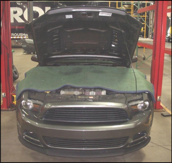
(Blanket will catch pins if dropped and metal debris while drilling.)
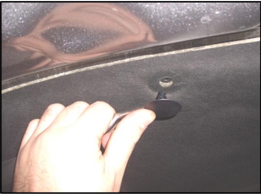
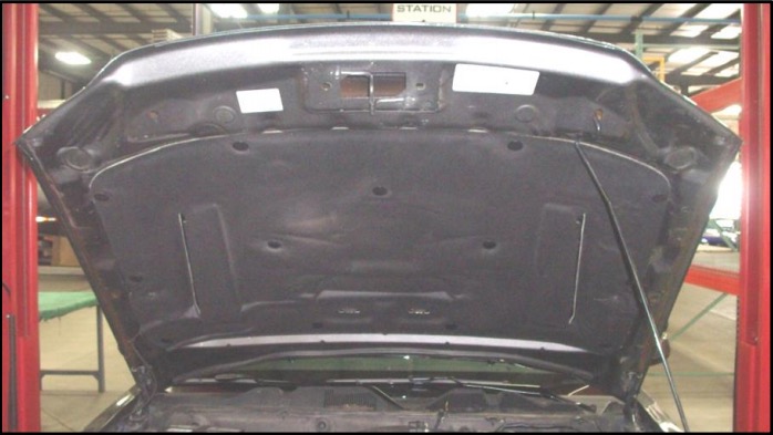
2. Using a suitable trim tool, remove the thirteen (13) hood insulator retainers, save for reinstallation. Remove the hood insulator once retainers are removed.
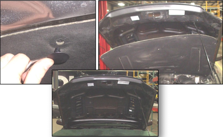
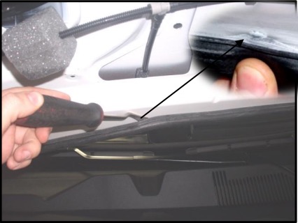
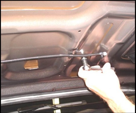
3. Using a suitable trim tool, remove the hood to cowl seal. Use caution when removing to not damage the rubber seal.
SECTION B – MODIFICATION
1. Prepare your template; make the necessary cuts along the dashed lines to align the template to the hood.
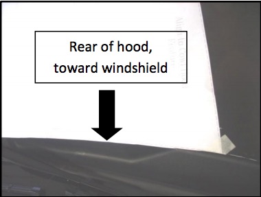
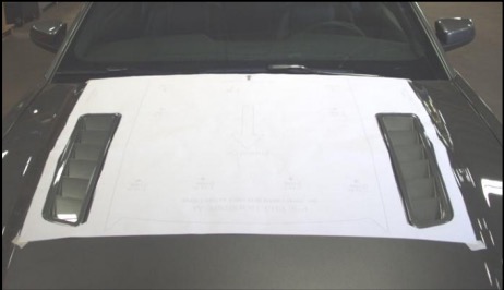
2. Set the hood down, unlatched. After cutting the template along its dashed lines, align the rear of the template to the rear of the hood. Align the sides of the template with the cowl hood features in the hood. If the vehicle is equipped with extractors, align the template cut outs with the extractors.
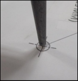
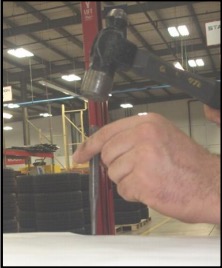
3. Tape the template down on the four (4) corners to prevent lifting while center punching the holes. Using a center punch and hammer, mark the holes to be drilled.
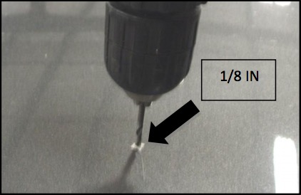
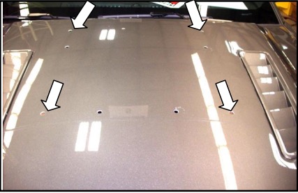
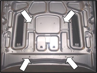
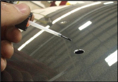
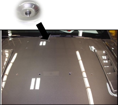
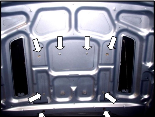
4. Remove template. Using 1/8” pilot drill bit, drill nine (9) holes into previously center punched marks on the hood. Continue drilling a straight, centered pilot hole through the second layer of sheet metal in the four (4) locations illustrated below.
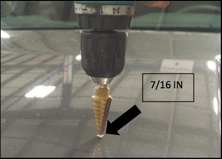
5. With a commercially available drill bit set (or a step drill bit), begin drilling the pilot holes open, working up to a size 7/16 IN drill bit. Do not drill the second layer sheet metal pilot holes open at this time.
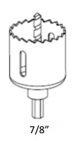
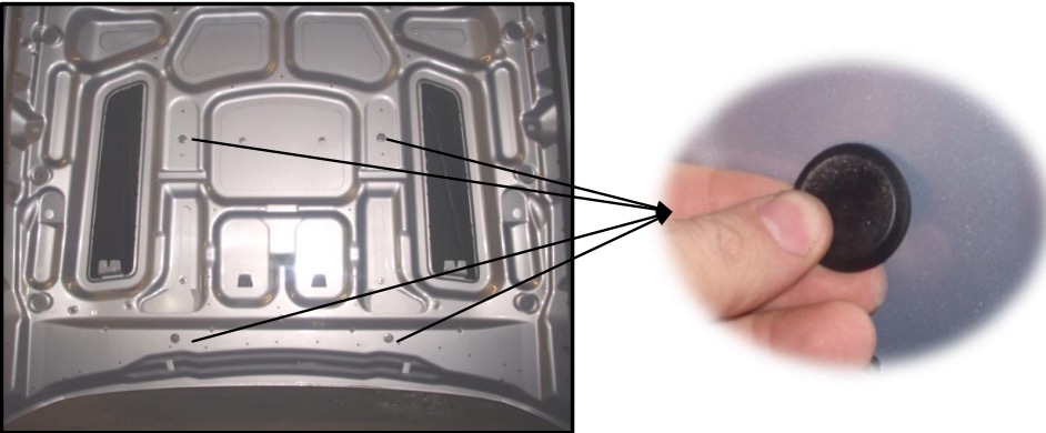
6. Open the hood. Using a suitable hole saw or drill bit, open the four (4) 1/8” pilot holes on the underside of the hood drilled in step 4 to 7/8”.
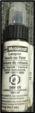
7. With commercially available clear coat, paint the exposed metal to prevent corrosion. (Motorcraft Part Number: PM-19500-6000)
SECTION C – Hood Scoop Preparation
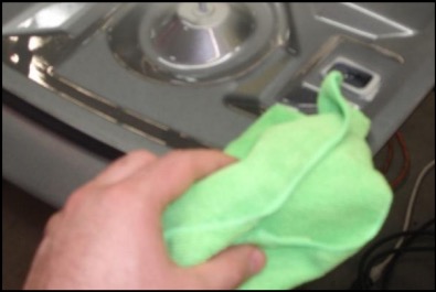
1. Remove hood scoop from packaging. If equipped, remove protective tape from edges. With household isopropyl alcohol and a terry cloth, clean the surface to apply the graphics and tape.

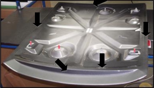
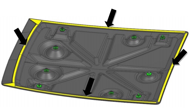
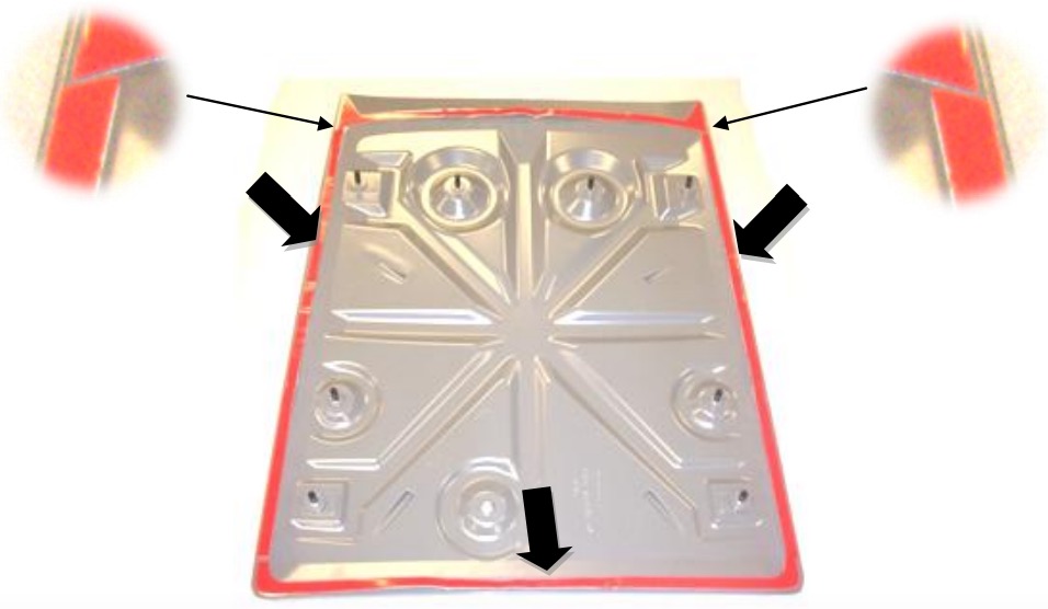
2. Apply supplied 3M Adhesion Promoter 4298 (P/N: 021200-27571) to the cleaned surfaces highlighted in white in the picture below. Let the Adhesion Promoter dry for at least 60 seconds before applying tape.
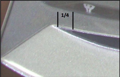
3. While adhesion promoter is drying, install the inlet graphic. Remove the backing from the inlet graphic and install starting 1/4 IN from the edge of the corner where the faux inlet starts. While applying the graphic run your fingers or a credit card along the surface to prevent any air pockets.
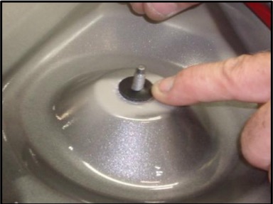
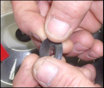
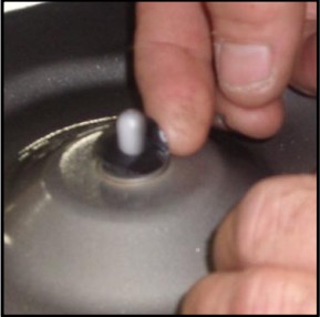
4. Remove the stud protectors. Remove the backing from eight (8) of the circular isolators and install around the eight (8) stud posts. Remove the backing from the ninth (9th) isolator and stretch it, so it fits around the locating dowel.
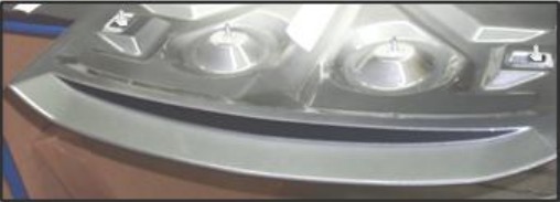
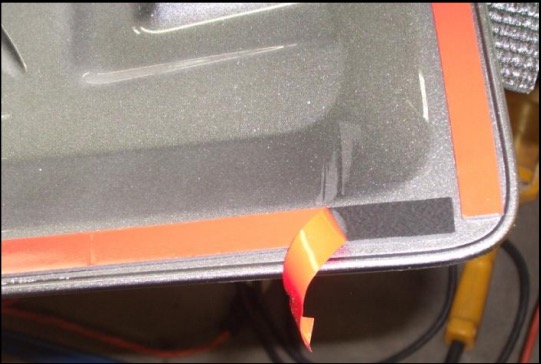
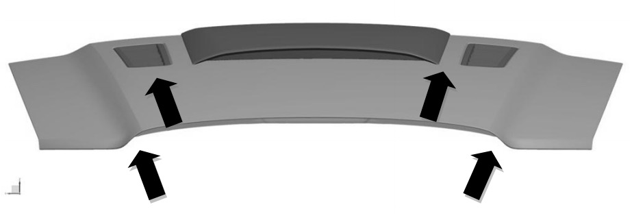
5. Install the front tape piece first by removing the white film and applying it with the triangular features close to the raised edge of the piece as shown in the picture below.
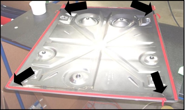
6. Next, install the rear tape piece, followed by the left and right tape pieces (left and right pieces are of equal length. The front portions are angled to follow the shape of the front tape piece). Equally space the side tape pieces between the front and rear tape pieces.
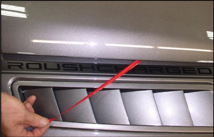
7. Pull approximately one inch of red tape from left, right and rear pieces of tape to allow for removal of tape once installed. Bend the tabs over for access to remove once hood scoop is in place.
SECTION C – Installation
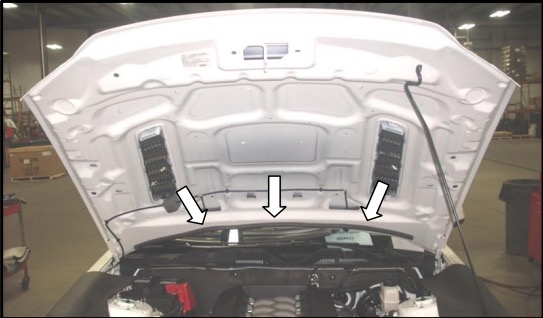
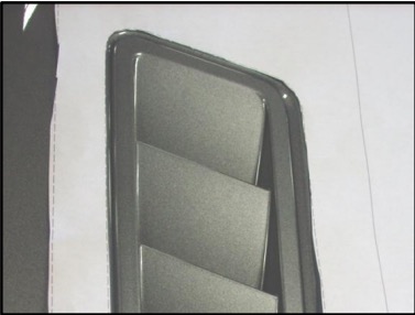
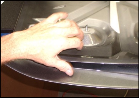
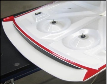
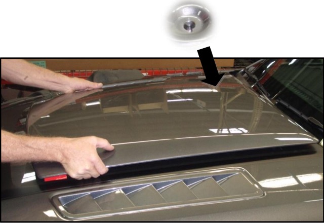
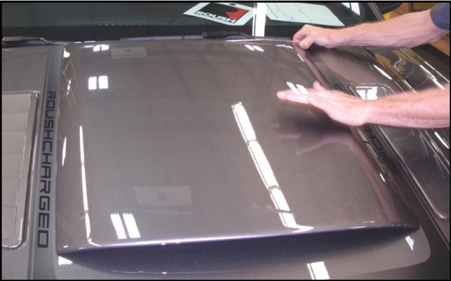
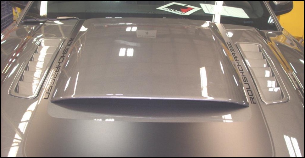
1. Holding hood scoop from the front, place the hood scoop over the hood. Place the rear locating dowel into the hole shown in the picture below.
2. Center the hood scoop between the cowl lines of the hood. If the vehicle is equipped with heat extractors, center the hood scoop between the heat extractors.
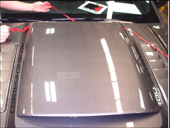
3. Set the hood scoop in its centered position, remove the red tape film; left and right side first, proceed with front, then back.
4. To properly set the tape, press firmly around the perimeter of the hood scoop.
5. Open the hood, hand install the eight (8) nuts (PN: W704521). Torque the eight (8) nuts to 4 NM (35 IN-LBS.)
6. Install the four (4) flush plugs (PN: 9750K25) into the 7/8” holes drilled on the underside of the hood.
7. Re-install the hood insulator. Install the nine (9) push-pins. Reinstall the hood to cowl weather strip removed in Section A, Step 3.
8. Remove the blanket and dispose of any metal shavings. Close the hood. Installation is now complete.
WARRANTY
All retail parts carry a 90-day warranty from the date of purchase. This warranty covers defects in materials or workmanship, and does not include (i) normal wear and tear, environmental conditions, improper installation; (ii) road hazards, misuse, abuse, neglect, accidents, collision, fire, theft, freezing, vandalism, riot, explosion, or objects striking the vehicle; (iii) misusing the vehicle, such as driving over curbs, overloading, racing, or using the vehicle as a stationary power source; (iv) altering, disassembling or modifying the parts; (v) defects caused or induced by failures, breakdowns, or damage by other parts, components or the vehicle; (vi) subjecting the parts to excessive moisture or water or any motor vehicle fluids (e.g.: oil, anti-freeze, battery acid, brake fluid, etc.); (vii) acts of God, natural disasters and other similar causes beyond the reasonable control of ROUSH; or (viii) application of chemicals that affect the parts. This Limited Warranty does not cover surface deterioration of paint, trim, and appearance items that result from use and/or exposure to the elements, such as stone chips, scratches, bird droppings, lightning, hail, windstorm, dings, dents, earthquake, road salt, tree sap, water or flood.
ROUSH SHALL NOT BE LIABLE TO REIMBURSE CUSTOMER/DEALER FOR INCIDENTAL OR CONSEQUENTIAL DAMAGES RESULTING FROM THE INSTALLATION OR USE OF ANY PRODUCT SOLD THROUGH THIS CATALOG OR ARISING OUT OF ANY BREACH OF WARRANTY. EXCEPT AS MAY BE STATED IN THIS CATALOG, ROUSH DISCLAIMS ALL EXPRESS AND IMPLIED WARRANTIES, INCLUDING THE WARRANTIES OF MERCHANTABILITY AND FITNESS FOR A PARTICULAR PURPOSE. IN NO EVENT SHALL ROUSH’S LIABILITY EXCEED THE PRICE PAID BY CUSTOMER/DEALER FOR PRODUCTS SOLD REGARDLESS IF ROUSH HAS BEEN ADVISED IN ADVANCE OF ANY POTENTIAL PROBLEM OR IF A CLAIM IS BASED ON CONTRACT, TORT, STRICT LIABILITY, PRODUCT LIABILITY OR OTHERWISE. SOME STATES DO NOT ALLOW THE EXCLUSION OR LIMITATION OF IMPLIED WARRANTIES OR THEIR DURATION, OR LIABILITY FOR INCIDENTAL OR CONSEQUENTIAL DAMAGES, SO THE ABOVE EXCLUSIONS OR LIMITATIONS MAY NOT APPLY.
