 FREE 1 to 3-Day Delivery on Orders $149+ Details
Simco Mustang Twin Gauge Pod Installation Guide
Installation Time
30 minutes
Tools Required
- 5.5mm Socket
- 7mm Socket
- 10mm Socket
- Ratchet
- 3/16" Drill Bit
- 3/8 Drill Bit
- Small Flat Head Screwdriver
- T15 Torx Bit
- Pliers
Installation
1. First disconnect the Negative (-) Battery Terminal and apply the Emergency Brake.
2. Remove the original Instrument Cluster from the vehicle by the following steps.
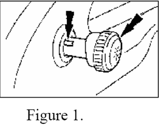
3. Remove the headlamp switch knob by inserting a narrow tool or standard screwdriver in the slot. Slide the screwdriver along the slot towards the end of the knob and pull the knob away from the dash to release the knob from the shaft. (See Figure 1)
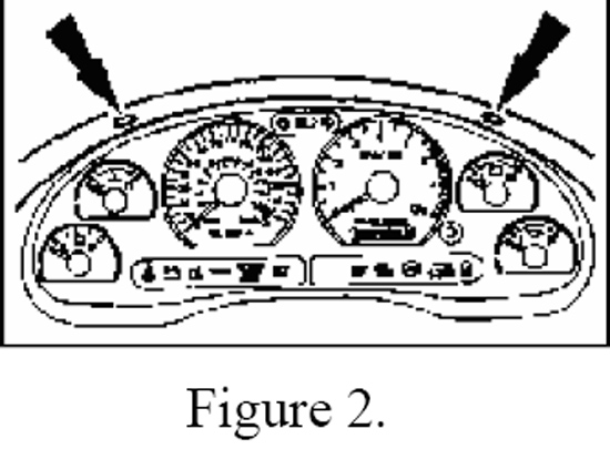
4. Remove two black Phillips screws from the top-inside of the instrument panel with a T-15 Torx or a 7mm Nut Driver depending on year of the car. (See Figure 2)
5. Carefully pull instrument panel trim away from the dashboard.
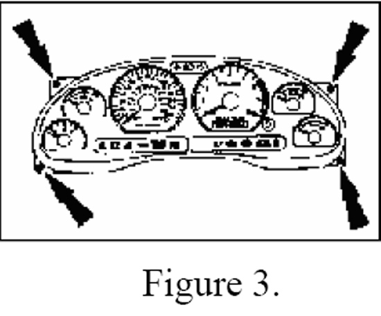
6. Remove four black Phillips head screws from the instrument cluster. (See Figure 3)
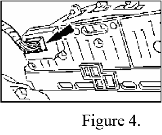
7. Disconnect the two electrical cables from the cluster by pushing the tabs in while simultaneously pulling connector from the cluster and remove the entire cluster panel. (See Figure 4)
8. Connect the supplied pressure sender to a boost pressure source with a 1/8 or ¼ NPT fitting and secure to the chassis to protect from movement and vibration.
9. Mount the Twin Gauge Pod on the dash by the following steps.
10. Position the supplied drill template on the center of the dash and space from the front of the dash as specified.
11. Tape the template to the dash and use a punch to mark the centers of the holes.
12. Drill three 3/16” holes for the attachment studs and one 3/8” hole for the wiring harness.
13. Thread the wiring harness through the 3/8” hole keeping ~4” on the connector side sticking out of the hole.
14. Pull the blue, white/blue, and shorter black wires under the dash to the instrument cluster opening and leave them hanging.
15. Route the gray and white/red wires through the dash to the passenger side foot-well area.
16. Route the long black wire to your pressure sender and connect.
17. Align the Pod with the holes in the dash and drop the unit into place.
18. Reaching through the instrument cluster opening, place the fender washers and nuts on the studs and tighten with a 10mm socket or wrench.
19. Remove the passenger-side kick panel and PCM to connect the harness wiring by the following steps.
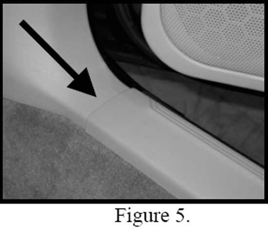
20. Remove the passenger-side door sill cover by pulling up at the edges. (See Figure 5)
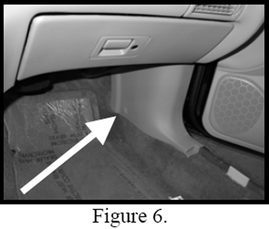
21. Remove the passenger-side kick panel by pulling at the edge to remove the Christmas tree-style fastener. (See Figure 6)
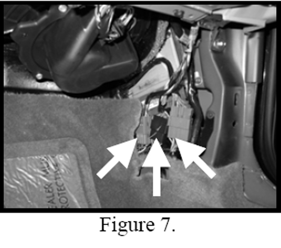
22. Pull the three connectors in front of the PCM for extra space by pulling sharply. Two have slide-style clips and one has a Christmas tree-style fastener. (See Figure 7)
23. Remove the 5.5mm bolt for the white plastic retaining bracket. (See Figure 8)

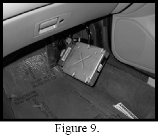
24. Carefully pull down on the PCM and rotate it so that it can be pulled outwards. (See Figure 9)
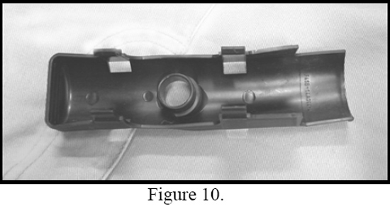
25. Remove the black plastic wire shield from the top of the PCM by unclipping the four clips with a small screwdriver. (See Figure 10)
26. The PCM harness connector is numbered on the edges for reference. Locate pin # 91 and the attached gray/red wire. With a supplied red quick splice connector, tap into this wire and connect to the white/red wire from the Twin Gauge Pod harness.
27. Locate pin #39 and the attached solid gray wire and connect to the solid gray wire from the Pod harness again with a quick splice connector. Make sure both wires have been properly placed in the connectors before pressing them closed with pliers. Secure any extra wire out of the way and replace PCM and paneling.
28. Connect the remainder of the wiring harness in the dash by the following steps.
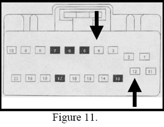
29. Locate the larger of the two connectors for the instrument cluster. Tap into the white/blue wire coming from the pin #12 as seen in Figure 11 and connect to the white/blue wire on the Pod harness using another quick splice connector.
30. Tap into the blue/red wire coming from the pin# 4 and connect to the solid blue wire on the Pod harness using another quick splice connector.
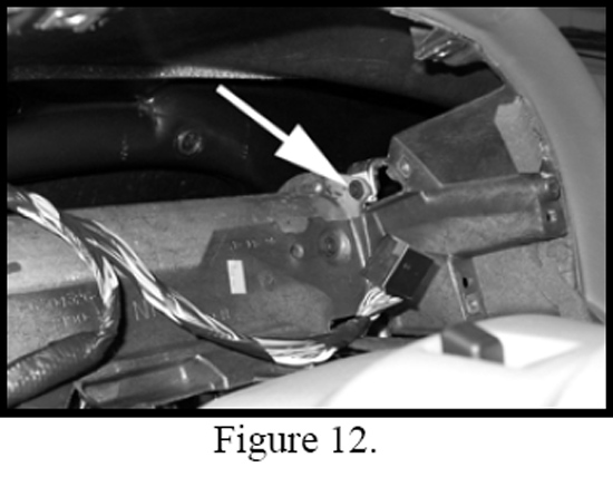
31. Loosen the screw on the dash bar at the far right of the instrument cluster opening. (See Figure 12) Attach the remaining black wire to this ground point. Secure the Pod harness wiring to the dash bar.
32. Re-install the instrument cluster and surround by following the reverse order of step 1.
Installation instructions provided by Simco Ltd.
Related Guides
-
Installation
-
Installation
-
Installation
