 FREE 1 to 3-Day Delivery on Orders $149+ Details
SLP Brake-Control Package ('07-'09 GT, GT500) - Installation Instructions

Shop Parts in this Guide
Installation
1. First drain the brake fluid from the master cylinder reservoir by either sucking the fluid out from the top or removing the rear brake line and letting the fluid drip into a cup. If the reservoir is not drained properly, brake fluid will drip onto you and the vehicles exhaust manifolds during the installation.
2. Next disconnect the negative battery terminal.
3. Next, remove the brake line that runs to the rear port of the master cylinder. To remove this line you must remove the nut that connects the line to the master cylinder and the nut that connects the line to the proportioning. See Photo 1 below for location of line in master cylinder.
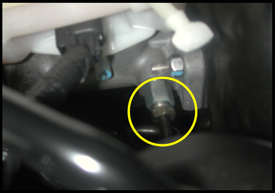
Location of Front Brake Line on Master Cylinder
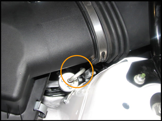
4. Remove the nut from the proportioning valve on the opposite side of the line nut removed from the master cylinder. Remove this stock line from the vehicle. See photo 2 below for location in proportioning valve.
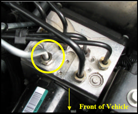
Front Brake Line Location in Proportioning Valve
5. On a work bench assemble SLP’s solenoid with the two included tube nut adapters (using Teflon tape on the 1/8” NPT side), tighten the two tube nut adapters.
6. Insert the master cylinder line into the vehicle by guiding the master cylinder end underneath the air conditioning lines and then towards the brake booster. Route the master cylinder line underneath the master and into the rear brake fitting. Note this line will easily slide into place, if you experience difficulty you may be routing it through the wrong location. Additionally, this line will also snap into the factory line clip that the factory line was removed from. See photo 3 and 4 for routing location.
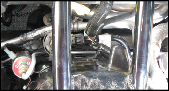
Master to Solenoid Routing Path SLP Brake Line Lock (07-09 GT 07-08 GT500) 4
Master to Solenoid Line Routing Path- Master View
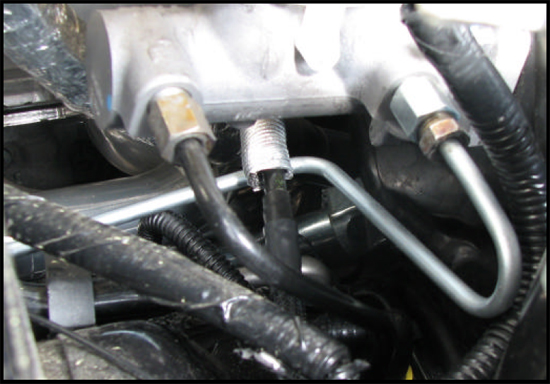
7. Next loosely install the proportioning valve to Solenoid brake line into the proportioning valve. Carefully route the line into the factory line clip as shown in Photo 5.
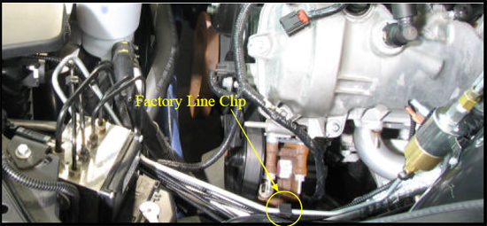
Proportioning Valve to Solenoid Line Routing
8. Next insert the solenoid between the two lines loosely(NOTE: Make sure the side marked MC is facing the Master Cylinder.)installed in steps 6 and 7. Position the solenoid so that both lines are relaxed and mark through the mounting holes to the fender with a sharpie where you will be drilling for the mounting screws.
9. Remove the solenoid and drill a pilot hole on each mark made in step 8.
10. Tighten down all brake line fittings.
11. Mount the solenoid to the fender using the supplied hardware.
12. Fill the reservoir with brake fluid.
13. BLEED THE BRAKE SYSTEM.
14. Next, install the supplied wire harnesses. Connect both wires to the two spade connectors on the solenoid by slipping the female spade connectors onto the male spades on the solenoid. Note: It does not matter which male spade you use to hook up either wire.
15. The harness with the inline fuse is to be routed across the front of the vehicle to the 12V bolt on the edge of the fuse box located on the passenger’s side. See Photo 6 below of 12V location.
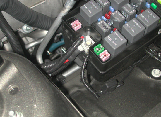
12V Power Supply Connection
16. The harness with the switch and ground wire attached is to run through the fire-wall into the vehicle where the switch can be mounted anywhere from the kick panel to the center console. A ½” hole will need to be made so that the switch can be mounted. To route the wire through the fire wall make a small hole in the hood latch cable grommet and feed the wires through that new hole. You will need to remove the switch from the wires to feed the wires through the hole made in the grommet.
17. Mount the ground wire with ring tongue terminal to a solid ground under the driver’s side kick panel.
18. The installation is now complete.
GT500 Supplemental Instructions
Note: These instructions are supplemental to the GT Mustang instructions and are to be used solely for the GT500 Mustang.
1. Follow instructions 1 through 7 as for the GT Mustang. It is important to note that the GT Mustang has a different fuel line routing then the GT500 therefore Photo 3 and 4 will not appear accurate. However this will not impact the position of the master cylinder to solenoid line so the line should be routed as detailed above.
2. Before the solenoid can be installed in the vehicle the solenoid bracket must be altered. Carefully place the solenoid on a suitable work table and gently tap both bracket tabs flat on BOTH sides. A vise will greatly aide this procedure, see photo 7below.
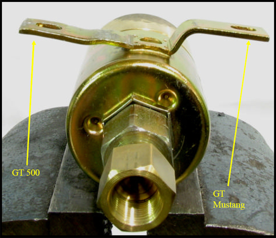
GT500 Solenoid Bracket Modification
3. Place the solenoid in between the SLP brake lines and snuggly tighten the fittings in the solenoid. Reinstall the intake tube and air filter housing to allow for correct adjustment of the lines and solenoid. Take a pair of tie wraps and temporarily make a loop around the master cylinder line to solenoid line. Tie this loop to the hood cable. Carefully pull the tie wraps so that the master cylinder to solenoid line will be pulled away from the intake tube about ¼”. Next remove the intake tube and air filter housing and then mark the holes for the mounting screws using a permanent marker. Remove the tie wraps from the SLP master cylinder to solenoid line and discard them. The solenoid will be mounted permanently with the supplied SLP screws in step 11, see photo 8 and 9 below.
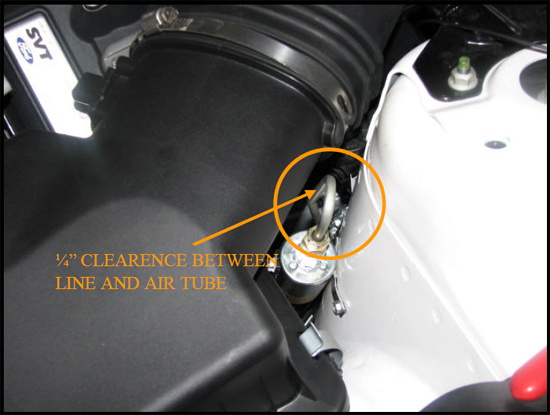
Line Lock Final Install Position
Clearance between Line and Intake Tube
4. Follow Mustang GT Installation steps 9 through 18 COMPLETELY.
Installation instructions provided by SLP
Related Guides
-
-
Installation
-
Installation
