 FREE 1 to 3-Day Delivery on Orders $149+ Details
How to Install Spectre Performance Cold Air Intake - Polished (05-09 GT) on your Ford Mustang
Tools Required
- Screw driver
- Phillips screw driver
- Socket wrench
- 10mm socket
- 13mm socket
- 8mm wrench
- 13mm wrench
- T20 torx

Shop Parts in this Guide
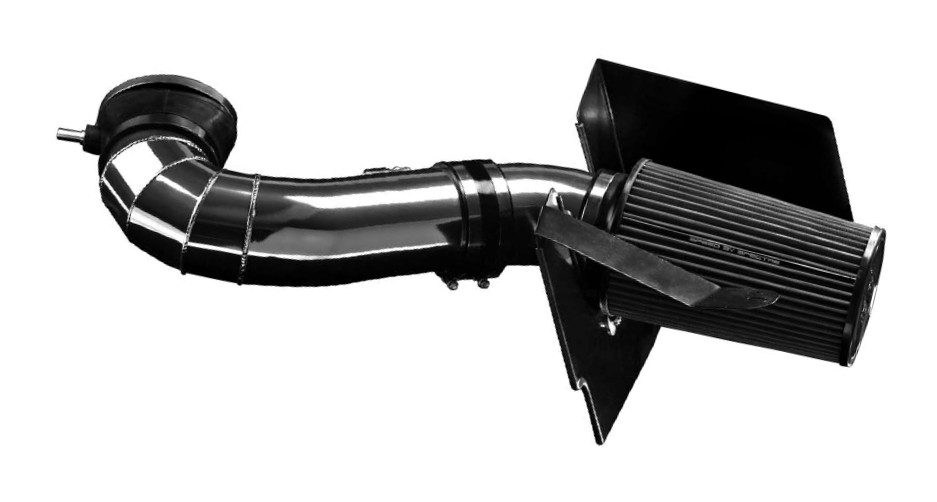
Parts List
1- Intake Tube
1- Intake Tube - short bend
1- Air filter
1- Oval coupler
1- PCV adapter tube
1- 4” coupler
4- 4” hose clamps
1- 5” hose clamp
1- Heat shield
1- Heat shield bracket
1- Rubber liner
1- MAF sensor calibration insert
1- Rubber mount
3- 8mm lock nuts
3- 8mm fender washers
1- M8x20mm hex bolt
2- Machine screws
5- M5 allen bolts
5- M5 washers
5- M5 lock nuts
1- M5 hex tool
Step 1: Safety first! Before you begin the installation, make sure that the vehicle is in park with the parking brake set. Disconnect the negative battery terminal and verify all components listed are present.
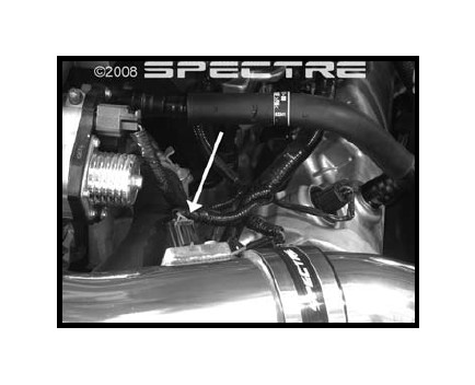
Step 2: Disconnect the PCV tube from the intake by pushing on the green tab and pulling the tube off. Disconnect the MAF sensor connector by sliding the red clip away from the tube and pulling the connector off of the sensor.
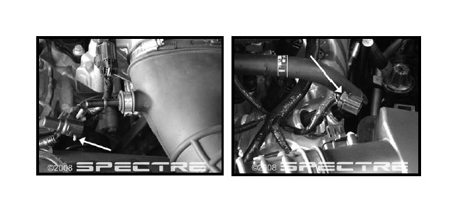
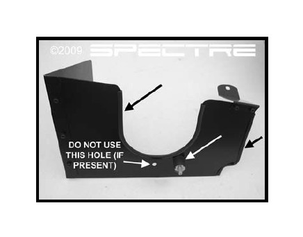
Step 3: Loosen the hose clamp on the intake tube at the throttle body. Remove the bolt on the air box housing, near the fender. Set the bolt aside for later use.
Step 4: Remove the intake and air box assembly and set it aside.
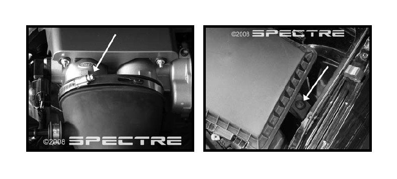
Step 5: Remove the plastic cover by loosening the two bolts shown.
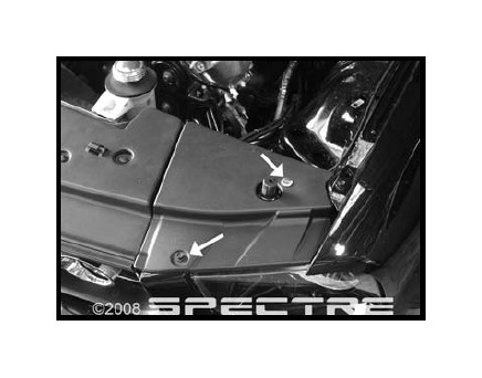
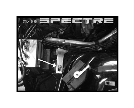
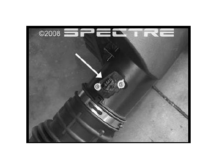
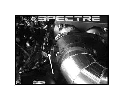
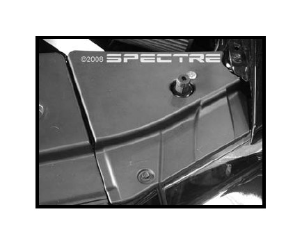
Step 6: Remove the bolt shown in the picture and set it aside for later use.
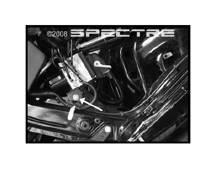
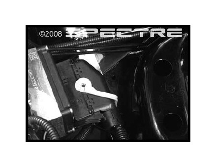
Step 7: Unlatch clip shown and slide counterclockwise to unlatch the connector. Move the connector to the side and remove the bolt shown in the picture. Set it aside for later use.
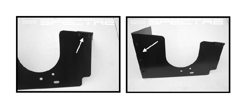
Step 8: Using the supplied M5 Alllen bolts, M5 flat washers and the M5 lock nuts, assemble the heat shield as shown. Tighten using the supplied M5 Allen tool and an 8mm wrench
Step 9: Install the rubber liner on the heat shield as shown (black arrows). Install the rubber mount, using the supplied fender washer and lock nut, in the hole as shown (white arrow).
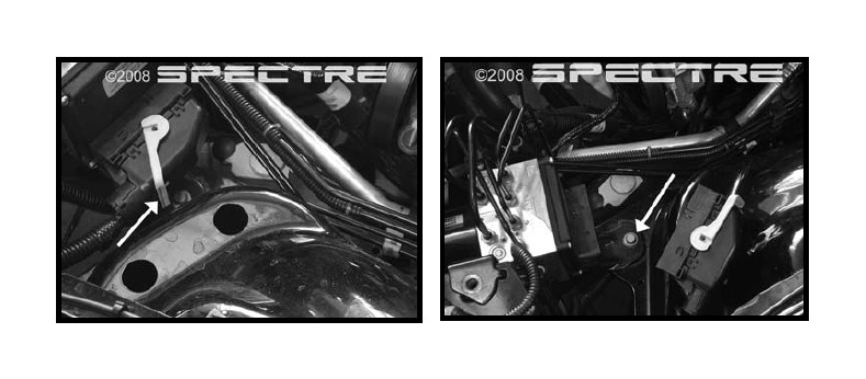
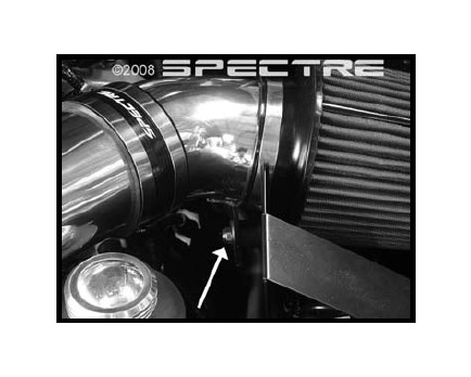
Step 10: Using the bolt removed in step 7, install the lower heat shield bracket as shown. Leave the bolt loose at this time.
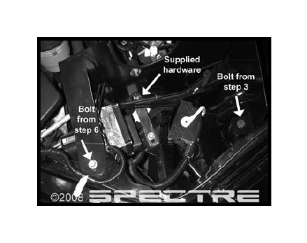
Step 11: Install the heat shield and secure it using the bolts removed in steps 3 & 6, and the supplied 8mm bolt, fender washer and lock nut as shown. Fully tighten all mounting hardware.
Step 12: Reinstall connector and slide latch clockwise to secure.
Step 13: Install the PCV fitting into the oval boot from the inside. Ensure that it is completely seated in the boot.
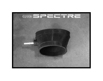
Step 14: Install the 5” hose clamp on the oval side of the coupler. Install the coupler onto the throttle body with the PCV tube pointing toward the passenger side. Fully tighten the clamp.
Step 15: Remove the mass air flow sensor from the stock intake tube.
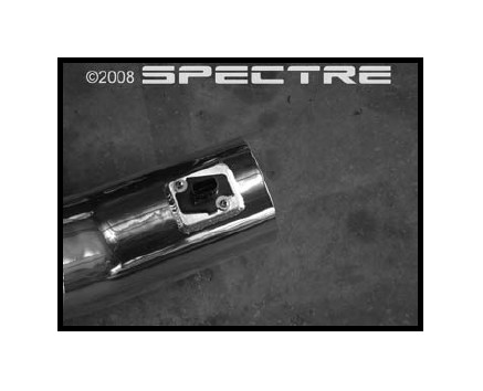
Step 16: Install the sensor in the new intake tube using the supplied Phillips head screws.
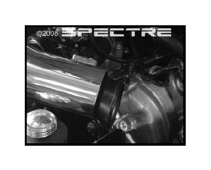
Step 17: Place a 4” hose clamp on the throttle body coupler and install the new intake tube as shown. Snug up, but do not fully tighten the hose clamp at this time.
Step 18: Insert the MAFS calibration tube as shown.
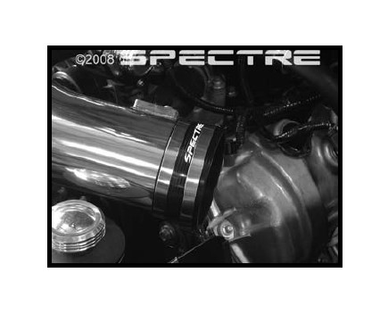
Step 19: Install the 4” coupler with two 4” hose clamps. With the coupler installed half way onto the tube, fully tighten the clamp which is over the tube. Leave the second clamp loose at this time.
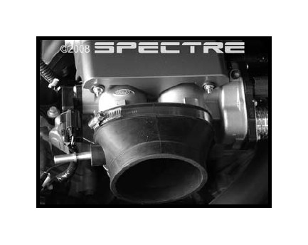
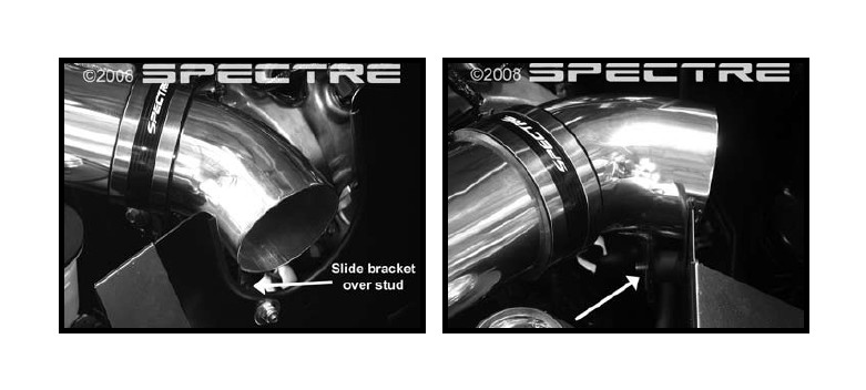
Step 20: Insert the short intake tube into the coupler. Slide the bracket over the stud on the rubber mount. It may be necessary to move the long tube in the throttle body coupler to allow for a proper fit. Once tube is in place, ensure that it is fully inserted in the coupler and fully tighten the hose clamp. Fully tighten the clamp on the throttle body coupler as well.
Step 21: Place a 4” clamp on the air filter and install it onto the intake tube. Fully tighten the clamp.
Step 22: Secure the intake to the rubber mount using a fender washer and lock nut.
Step 23: Reinstall the PCV fitting, ensuring that it is completely inserted with the green tab in the secured position.
Step 24: Reinstall the MAFS connector.
Step 25: Reinstall the plastic cover using the factory hardware.
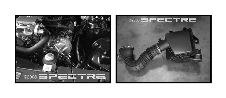
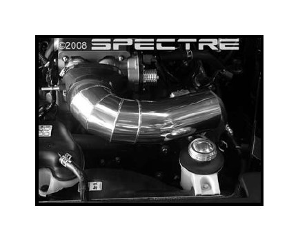
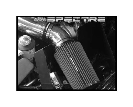
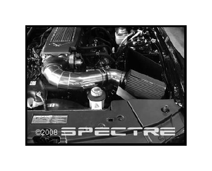
Step 26: Ensure that all hardware and hose clamps are fully tightened. Reconnect battery. The installation should look like this.
Step 27: Start vehicle and let warm up. Shut off and inspect the installation once more for any loose clamps or hardware. Test drive & enjoy!
