 FREE 1 to 3-Day Delivery on Orders $149+ Details
How to Install a SR Cold Air Intake for 1994-1995 Mustang GT
Installation Time
60 minutes
Tools Required
- Small flat-blade screwdriver Medium flat-blade screwdriver Ratchet - I used a 1/4" drive ratchet
- 5/16" socket
- 10mm deep and shallow sockets
- 10mm wrench

Shop Parts in this Guide
Installation
1. As with any car repair work make sure that the car is on a level and safe surface before starting your work. Begin by disconnecting the negative terminal of the battery and securing the cable away from the battery terminals.
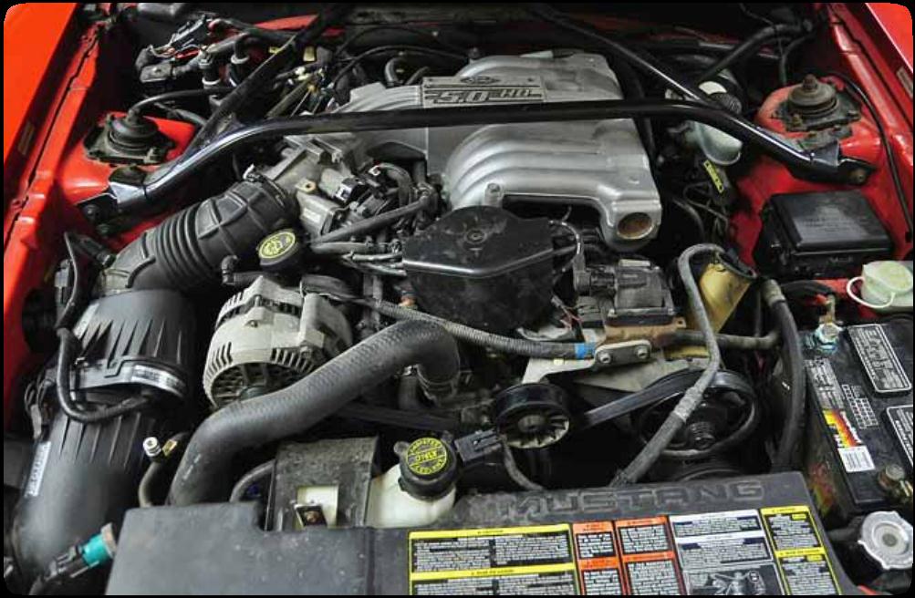
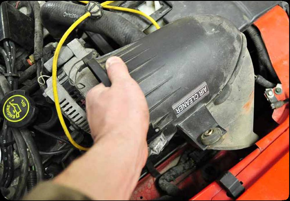
Before.
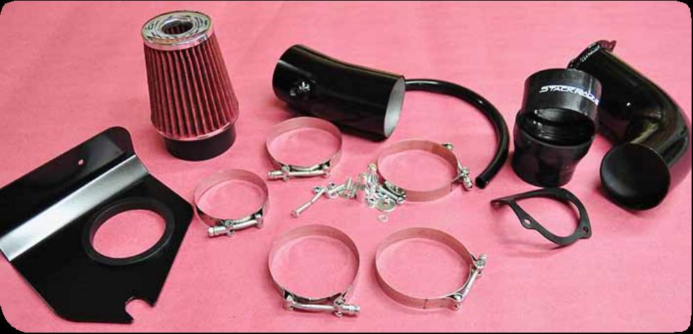
2. Unpack your air intake and familiarize yourself with the pieces. There are several band clamps plastic connectors aluminum tubes. Keep the pieces together and make sure the small hardware is somewhere that it won’t get lost.
3. It’s time to dig in. Take a good look at your engine. Note how the current air intake looks for future reference. The intake system from the throttle body to the filter box will be removed and replaced. Begin by loosening the band clamps that attach the intake tube to the mass airflow sensor using a flat blade screw driver or the 5/16” socket and ratchet.. There is a small hose clamp helping hold the air intake temperature sensor in - loosen that clamp too using a flat blade screwdriver.
Removing clamps that attach the intake tube.
4. Disconnect the air intake temperature sensor plug. It’s very easy to do - use the screw drivers to gently lift the tabs that lock the connector together. Work the connector apart.
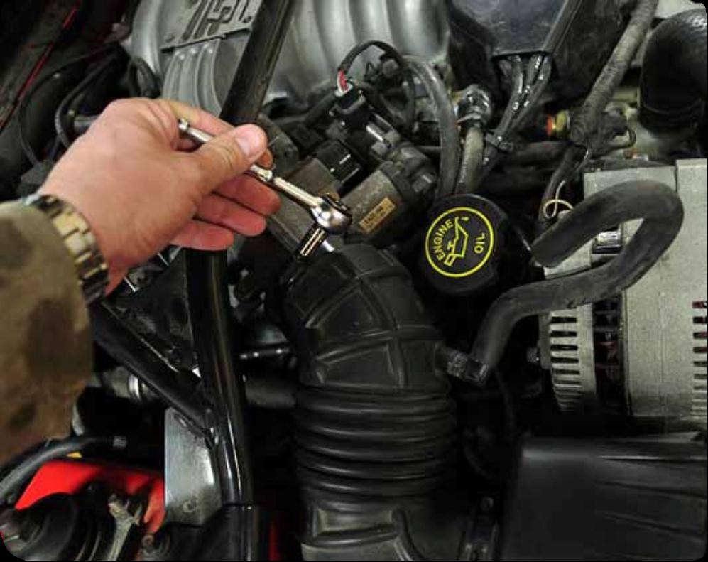
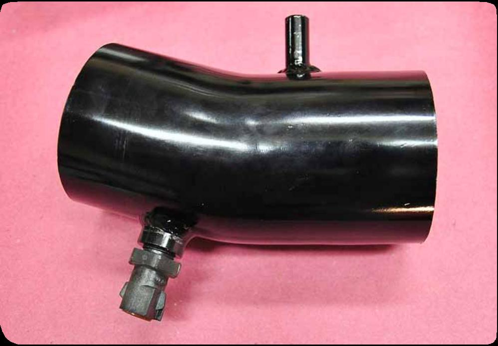
5. Remove the vent hose that connects the oil filler neck to the intake. Set the piece aside. A new hose comes with the kit but I opted to reuse my old one.
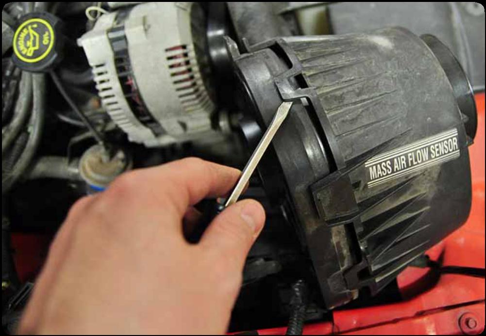
6. Move down to the airbox that houses the air filter. There are two clips that hold the airbox to the mass airflow sensor to create a seal between the two parts. The first clip is on top and easy to access. The second is lower on the housing on the engine side of the housing. Open both latches.
7. Work to separate the rubber intake tube from the mass airflow sensor. A little wiggling should free the tube.
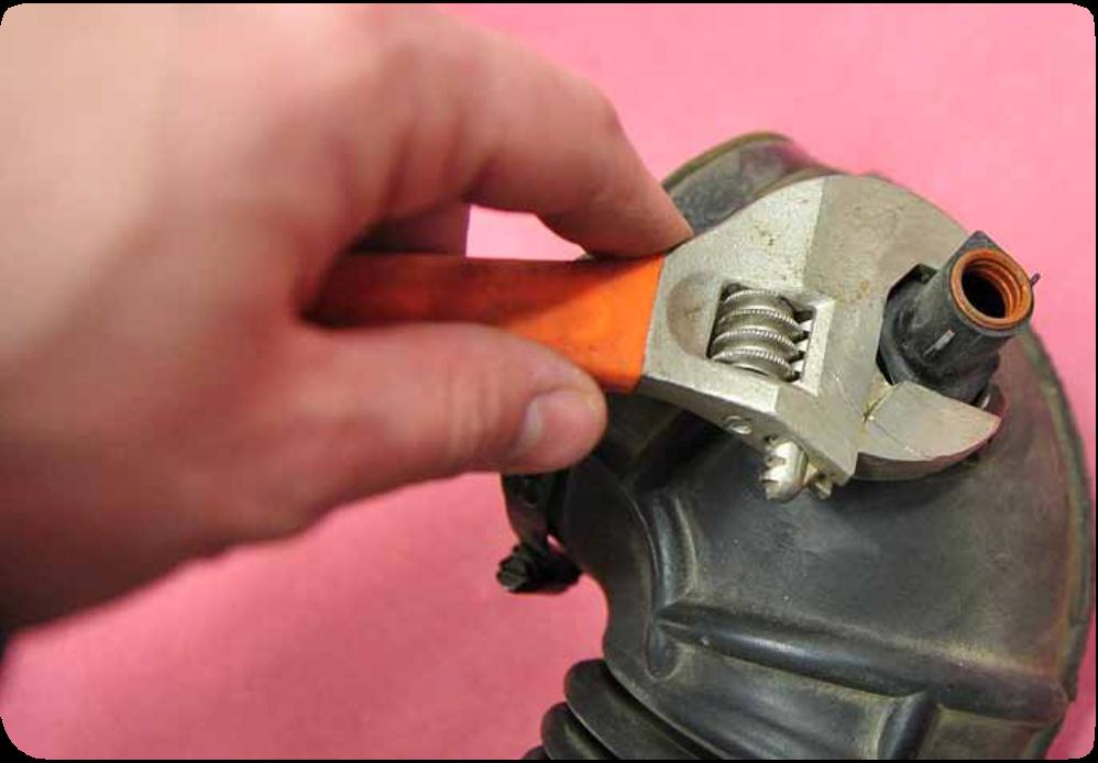
8. Using the adjustable wrench remove the air intake temperature sensor from the intake tube. Be careful with the sensor it is plastic and a replacement is about $40. After removing the sensor put it somewhere safe and clean - it will be reused. Put the intake tube aside it is no longer needed.
Keep the sensor it will be reused.
9. Time to remove the mass airflow sensor. Look at the wires that enter the housing then work down until you locate the plug that attaches it to the car’s wiring harness. Gently lift the clips and slip the plugs apart. You can now pull the mass air flow sensor from the engine bay. Be careful with the mass air flow sensor it will be modified slightly and reused later.
10. There should be one piece left to remove - the airbox. Take out the top bolt attaching the airbox to the inside of the fender. Slip the rubber grommet out of the airbox and put it aside - it will be used later. There are no more bolts holding the airbox in but it can be a bit stubborn to remove. The bottom of the airbox is pushed into rubber grommets on the bottom. Pull up on the airbox hopefully it will let loose if not try some twisting and wiggling. Once the airbox is freed put it in a box with the other Mustang parts that will never be used again but somehow none of us can throw away.

Airbox removal
11. The engine bay should be wide open. Before we start adding the new parts we need to do a little reassembly. Locate the new tube that has a threaded hole. Thread the air intake temperature sensor into the hole. Use the adjustable wrench to tighten the senor. It needs to protrude completely into the tube. Be careful and go slow the sensor is plastic. This step may seem a little out of sequence but screwing in the sensor will keep it from becoming misplaced or damaged.
The sensor is installed in this image.
12. The mass air flow sensor needs to be used with the new intake tube but it needs some work first. The actual mass airflow sensor is inside a plastic housing and it’s easy to remove. The housing is made of two halves attached by plastic clips similar to the wiring connectors only larger. Use the medium flat blade screwdriver to gently pry up the clips and separate the two pieces. Add the pieces to your box of useless parts.
Opening the mass air flow sensor housing
13. Using the ratchet and 10mm deep socket remove the nuts that attach the mass air flow sensor to the housing. Push the rubber grommet that protects the wire through the housing so that the wire connectors can pass through the hole in the housing. Pull the mass airflow sensor away from the housing and put the rest of the housing aside. Remove the screen from the from of the mass air flow sensor.
14. The curved tube will bolt to the mass airflow sensor. Begin by placing the rubber gasket on the mass airflow sensor. Align the tube to the sensor and use the supplied bolts washers and nuts to attach the parts. Tighten the bolts in an X pattern to make sure it is evenly torqued.
Intake tube with mass air flow sensor installed.
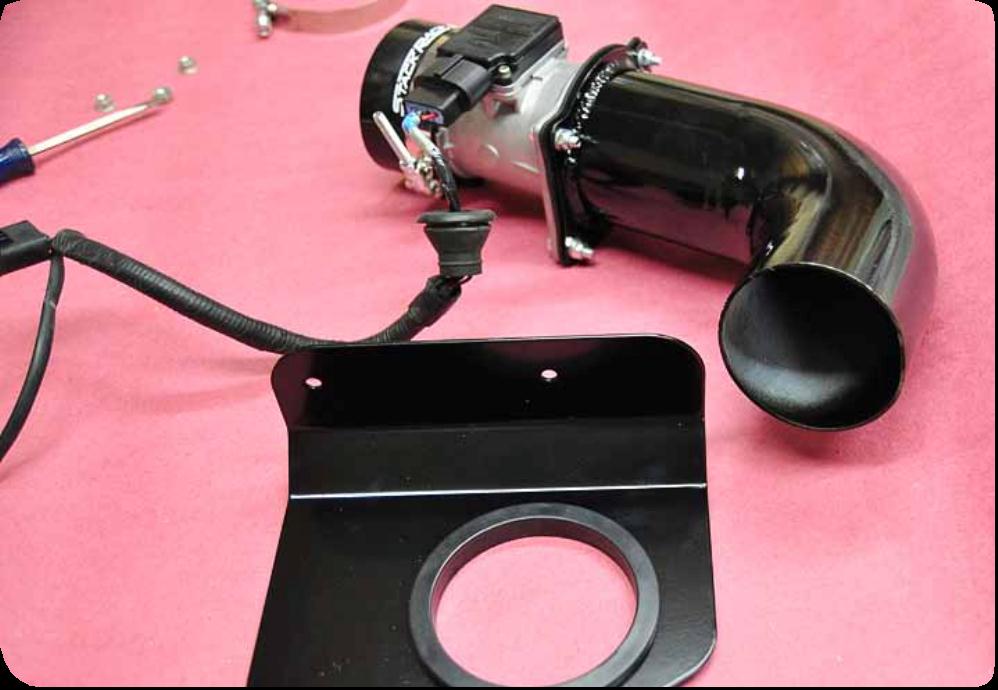
15. The steel plate with the large hole in it is a support for the intake tube. Slip it over the curved tube with the flange facing toward the mass airflow sensor. Now slip one of the large band clamps on the tube and add the air filter. Slide the filter onto the tube and slide the clamp onto the filter. Tighten the clamp firmly but don’t crush the rubber on the filter or the tube.
Filter and mass air flow sensor installed.
16. Add a rubber connector to the end of the mass air flow sensor. Put a band clamp over the end and prepare to tighten it. Think about the direction the bolt-end of the clamp will be facing - make sure offers plenty of clearance on the engine-side of the tube. Tighten the clamp.
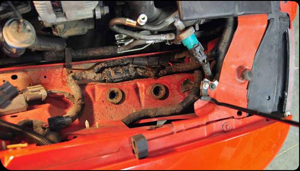
17. Before we slip the mass air flow sub assembly in place locate the two metal plugs that came with the intake system. The plugs slip into the rubber grommets that held the air box in place. The hole faces up to accept bolts from the bracket that will support the intake.
Rubber grommets that will accept the support bracket.
18. Support the entire subassembly and lower it into place. The air filter goes in the hole in the fender. The holes in the bracket must be close to aligning with the small holes in the bottom of the bracket. Be patient and gentle with the subassembly. Be careful not to damage the mass airflow sensor wiring or the filter during this process
Lower end of tube with filter installed.
19. Line up the bolt holes in the bracket with the holes in the metal plugs below it. Insert the supplied bolts and tight them. Downward pressure on the bracket will keep the plugs from turning in the holes and allow the bolts to be tightened using a ratchet with 10mm socket or a 10mm wrench.
20. On the top of the bracket there is a U-shaped gap that will accept the rubber grommet from the old air box. The grommet was on the top of the old airbox - just pull it off and slip it into position and tighten the bolt that holds it in place. My car was missing the bolt I still need to replace it.
21. Reconnect the wiring for the mass air flow sensor in the opposite way it was disconnected. The plugs only fit one way so look closely at them before attempting to reconnect them.
22. Locate the rubber coupling that has two different size ends. Slip the small band clamp onto the small end then fit the end over the throttle body. If it doesn’t want to go on try a little universal lubricant - spit - on the rubber coupling. Tighten the band clamp to hold the coupling in place making sure to orient the clamp in a convenient direction.
23. Insert the final tube between the two couplings making sure to first put band clamps in place on each end. Slip the tube in place orienting it like shown in the photo. Sliding something smooth like a screwdriver blade along the edge of the rubber coupler can help it slip into place. Be careful not to score or tear the rubber. Don’t tighten the clamps until you have reconnected the intake air temperature sensor and the hose connecting the oil filler neck to the intake tract. As I mentioned earlier I opted to reuse the hose because it was in great condition and prevent to a convenient shape.

Make sure the band clamps don’t interfere with other engine components
24. Reconnect the negative battery cable and double check the engine for stray parts and tools. Test drive and enjoy.
Related Guides
-
Installation
-
Installation
