 FREE 1 to 3-Day Delivery on Orders $149+ Details
How to Install a Push Button Start Ignition Kit in your 2005-2010 Mustang
Installation Time
2 hours
Tools Required
- Phillips head screwdriver
- Flat head screwdriver
- Ratchet
- 7mm Socket
- Torx T20 bit
- Wire strippers/cutters
- Hand file
- Needle nose pliers

Shop Parts in this Guide
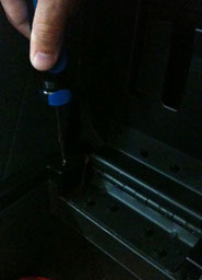
1. Start by removing the (2) Phillips head screws at rear of the center console under the armrest. (Figure 1).
Figure 1
2. Remove the Shifter boot (Manual) or Shifter Handle (Auto). (Figure 2).
Figure 2
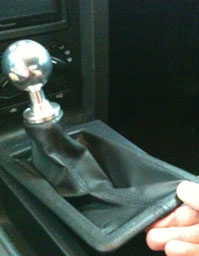
NOTE: Manual transmission cars are required to remove the shift knob first by unscrewing it counter-clockwise.
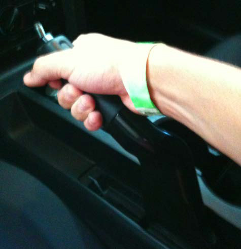
3. FULLY extend E-Brake for enough clearance of the center console. (Figure 3).
Figure 3
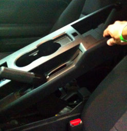
4. Lift the center console cover starting from rear and sliding it over the E-Brake handle. (Figure 4).
Figure 4
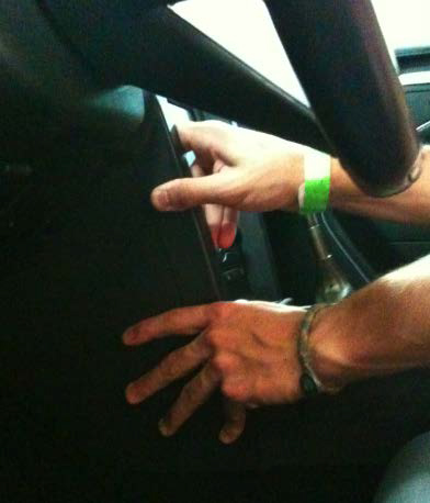
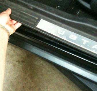
5. Remove the side cover from the dash panel located on the driver side. It is held in place by clips, and can easily be removed by grabbing the cover and pulling straight back. (Figure 5).
Figure 5
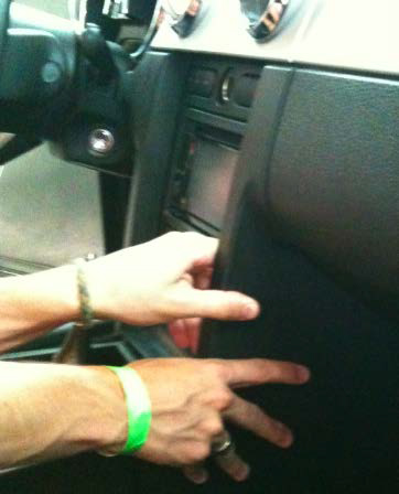
6. Repeat the same for the passenger side cover also. (Figure 6).
Figure 6
7. Remove the (6) screws retaining the radio trim plate using a 7mm socket and ratchet.
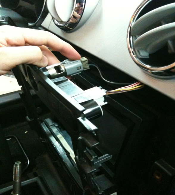
8. Remove the (3) plugs behind the radio trim plate, which can be easily removed by depressing the tabs on each plug. (Figure 7).
Figure 7
9. Remove the connector located on the passenger side of the radio trim plate. It can be removed by lifting the locker lever shown in (Figure 8a and 8b).
NOTE: The following pictures were taking from the driver’s side for easy identification.
Figure 8a
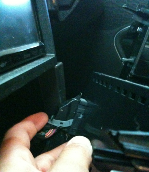
Figure 8b
10. Remove the remaining connector at the bottom of the radio trim plate, which is located on the driver’s side.
11. Remove the radio trim plate
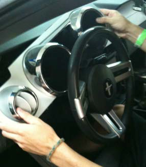
12. Remove the instrument cluster trim plate. It is held in by clips and can be removed by firmly grasping it and pulling outwards, which is shown in Figures 9a, 9b, and 9c.
NOTE: This step is not mandatory but makes for easier access to route the wires from the START ENGINE push button to the ignition switch connector.
Figure 9a
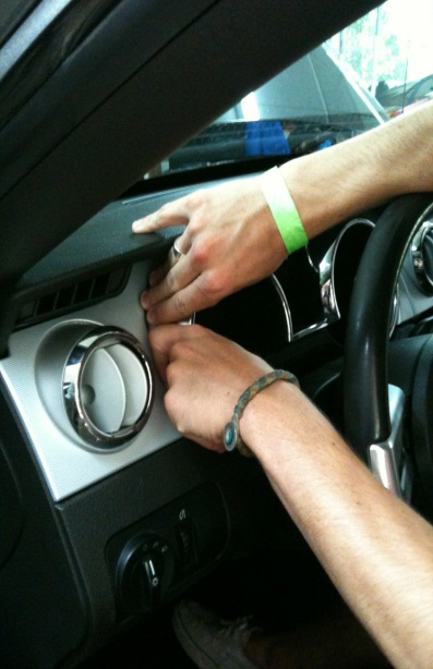
Figure 9b
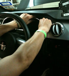
Figure 9c
13. Remove the driver side rocker panel. It is held in by clips and can be removed by pulling panel straight up. (Figure 10).
Figure 10
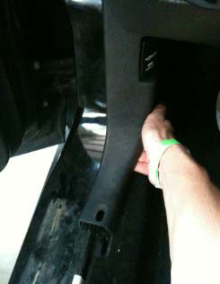
14. Remove the driver side kick panel by grasping it and pulling straight back. (Figure 11).
Figure 11
15. Remove the (2) screws located beneath the dash panel using a 7mm socket and ratchet.
16. Remove the lower dash panel cover. (Figure 12).
NOTE: Remove the (2) connectors that attach to the headlight switch, which can be easily removed by depressing the tabs as shown in (Figure 13).
Figure 12
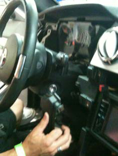
Figure 13
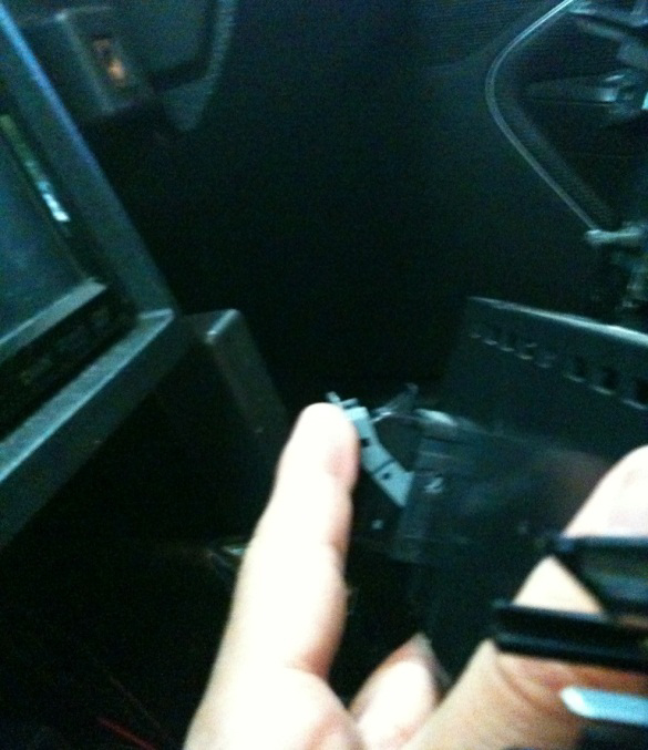
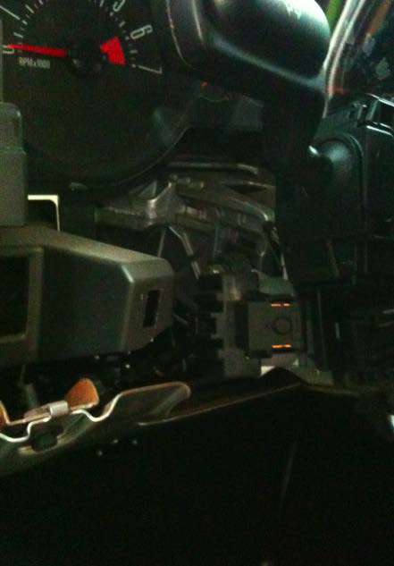
17. Remove the lower steering column cover by removing the (3) Torx T20 screws. By doing so this exposes the ignition switch connector on the left hand side of the steering column. (Figure 14).
Figure 14
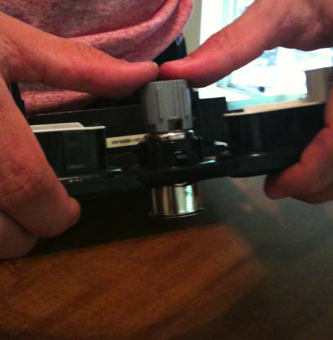
18. Prepare the radio trim panel so the START ENGINE push button will fit flush.
-First start by removing the 12V power supply receptacle.
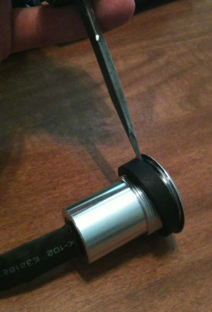
-Locate the locking tabs retaining the cylinder with inside the plastic ring.
-Using a small flat head screwdriver, pry the locking tabs away from the plastic ring. (Figure 15).
-It will be necessary to damage the plastic ring for removal because the plastic retaining ring will not be re-usable.
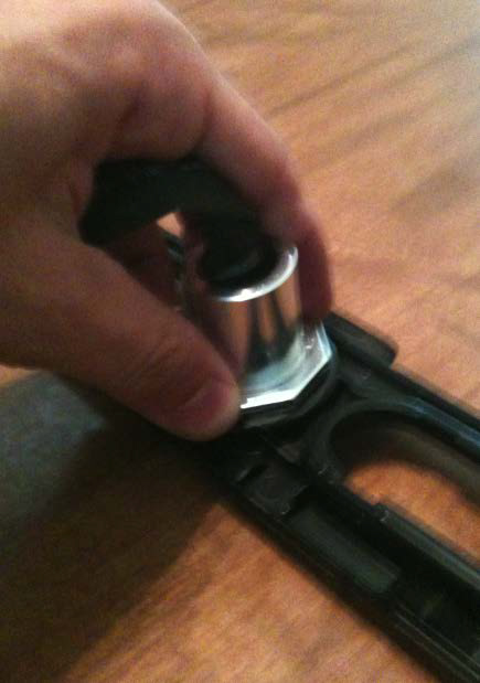
20. Once the locking tabs have been removed, press the cylinder out from the radio trim panel. (Figure 16).
Figure 15

Figure 16
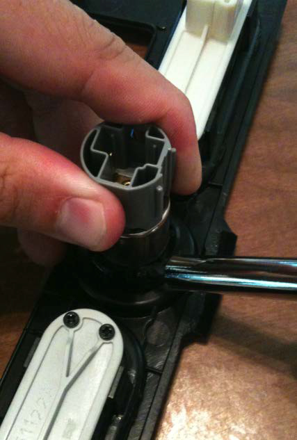
21. Remove the remaining plastic ring from the mounting hole on the radio trim panel. Using needle nose pliers ease in the removal of the ring. (Figure 17).
Figure 17
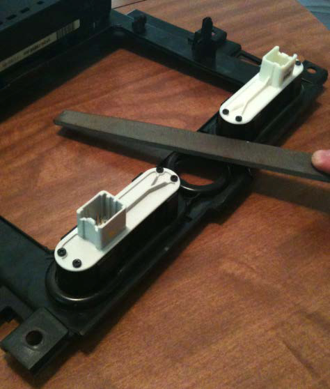
22. Using a hand file, remove some material off the backside of the mounting hole before installing START ENGINE button.
-It is located on the bottom of the mounting hole on the backside. (Figure 18).
-There needs to be enough clearance so threads on the button are locked onto by the locking nut.
Figure 18
23. Install the spacer onto the ENGINE START button positioning it so the recessed step of the spacer and button line up and fit together. (Figure 20a and 20b).
Figure 20a
24. Place ENGINE START button into mounting hole of radio trim plate and tighten locking nut ^
Figure 20b
25. Attach supplied quick splice crimp connector to ENGINE START button connector.
26. Reinstall radio trim plate, while directing wiring harness towards ignition switch connector referred to in (Figure 14).
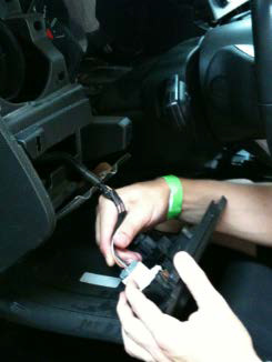
27. Disconnect ignition switch connector by releasing tab.
28. On ignition switch connector, the GREEN wire on the far outside will need to be cut from ignition switch connector.
-Attach GREEN wire to either quick splice crimp connector of ENGINE START button connector. It does not matter which one you use.
NOTE: Failing to cut this wire will allow vehicle to still be started by the key.
NOTE: For 2010 models, use the BLUE wire with a WHITE stripe.
29. On opposite end of GREEN wire there is a WHITE wire with a YELLOW stripe on far outside. SPLICE into remaining
wire from ENGINE START button with quick splice crimp connector. DO NOT CUT THIS WIRE.
NOTE: For 2010 models, use LIGHT GRAY wire with a PURPLE stripe.
30. Re-attach all of the above necessary connections and re-install radio trim panel using the (6) screws removed during disassembly.
31. Re-attach negative battery cable.
32. Confirm your vehicle is in Neutral or Park, and test installation by starting your vehicle. Turn the key into the RUN position for the ENGINE START button to work.
32. Once all function of working properly, re-install dash panel and center console in reverse.
33. Enjoy your ENGINE START button!
Installation Instructions written by AmericanMuscle customer Laurence Arroyo 6.21.12

