 FREE 1 to 3-Day Delivery on Orders $149+ Details
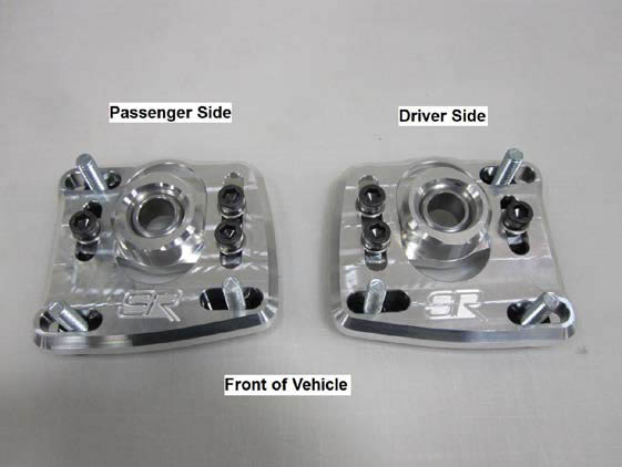
How to Install SR Performance Caster Camber Plates on your 1994-2004 Mustang
Installation Time
4 hours
Tools Required
- Jack and Jack Stands
- Air Powered Impact Wrench (recommended but not necessary)
- Other Tools

Shop Parts in this Guide
Note: You must have your car aligned after installation of the camber plates. If installing plates before driving to a shop for alignment, measure strut position before beginning and get strut as close to starting position as possible when installation is complete.
Take Note of Driver/Passenger Side Orientation Before Beginning Installation
Step 1:
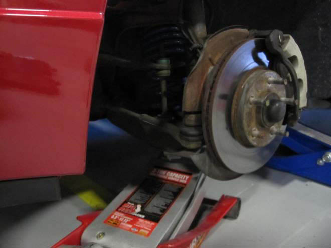
Support the front of the vehicle with jack stands
under the front frame rails. Place a floor jack
under driver’s side control arm and raise slightly
to take the weight off of the strut.
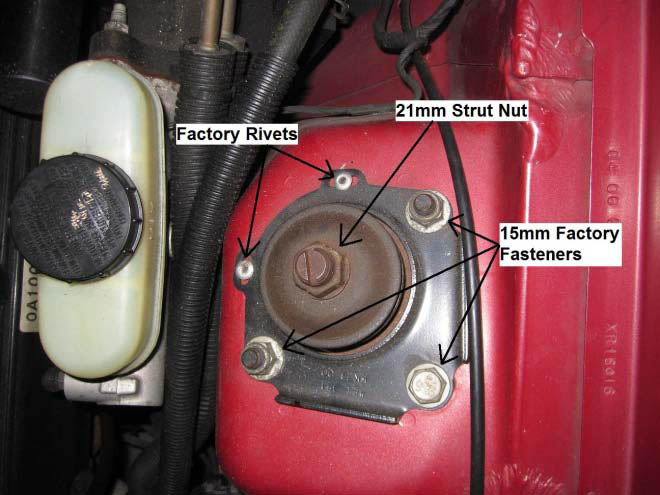
Step 2:
Use a drill or chisel to remove rivets (if still in
place), remove upper 21mm strut nut, and
remove 15mm factory plate fasteners. Note:
Removing the upper 21mm strut nut is easiest
with an air powered impact wrench.
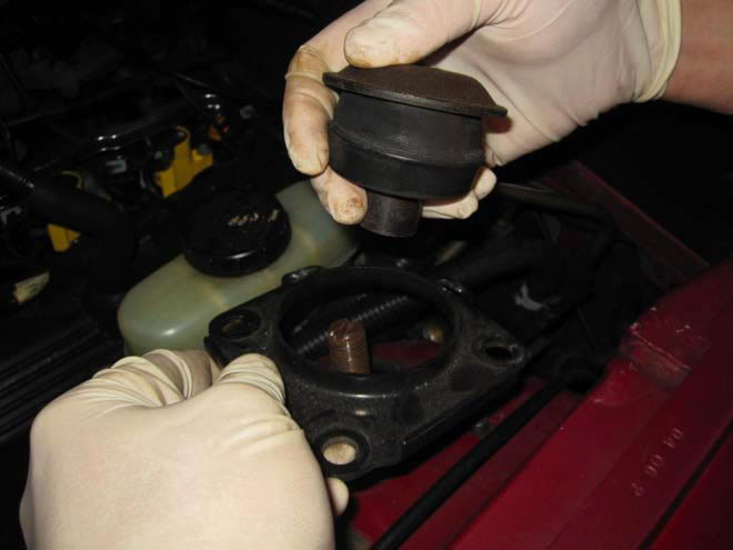
Step 3:
With the factory plate loose, remove the upper
strut washer, rubber strut bushing, and upper
factory plate as shown.
Step 4:
Slowly lower the floor jack supporting the lower
control arm, letting the strut fall as far as
possible down in the strut tower. Reach in the
fender well and compress the strut, moving it
from the shock tower into the inner fender well.
Once in the fender well, remove the factory
lower plate.
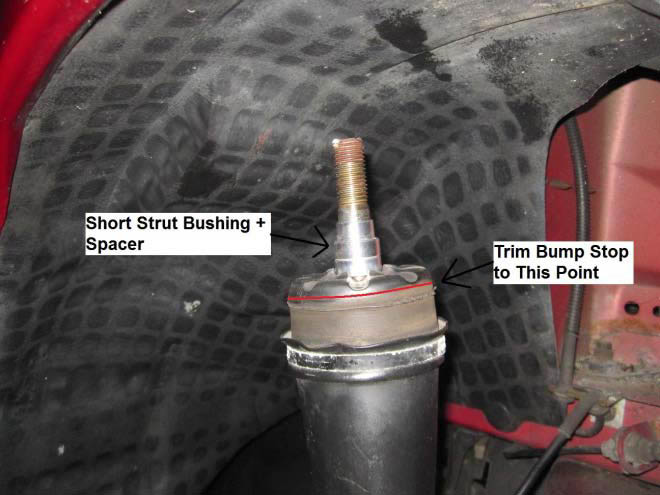
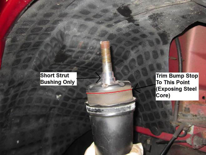
Step 5:
There are four different options for strut
spacing with your camber plates. Most cars will
use Option 2 (Cars lowered .5” - .75”) or Option
3 (Cars lowered 1” – 2”). Once the correct
spacing is determined, install the spacers as
shown below:
Note: These spacing option are simply
guidelines, cars may vary for a number of
reasons. If you experience bottoming problems
once the plates are installed, raise the strut to a
higher mounting position.
Option 1: This lowers the strut mounting point
from a stock setting. This setting is used when
shorter than factory height struts are used with
factory height springs.
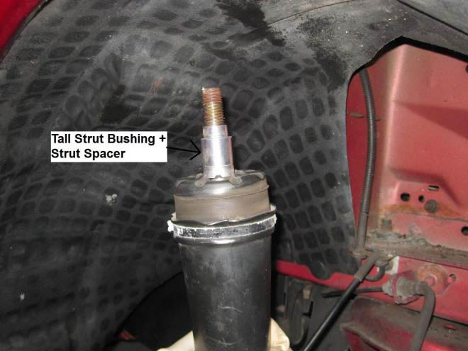
Option 2: This raises the strut mounting point
from a stock setting. Use with cars at stock
height to cars slightly lowered (.5” - .75”).
Note: In order to run the Option 3 or 4 setting,
you must trim the top of the rubber from the
bump stop to the indicated red line in the
photos below. This will prevent the rubber from
interfering with the underside of the strut
tower. You can use a hacksaw, Sawzall, etc to
cut the excess rubber
Option 3: This raises the strut mounting point
from a stock setting as well. Use with cars
lowered 1” – 2”.
Option 4: This setting should only be used
when experiencing strut bottoming problems
due to lowering springs with too soft of a spring
rate. It is necessary to remove all of the rubber
from the bump stop at this setting, and may
require grinding some of the steel down as well.
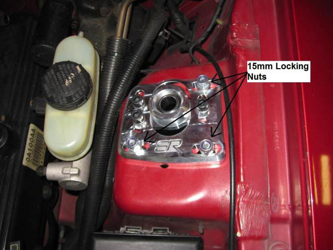
Step 6:
Install the drivers side stud plate in the strut
tower from inside the fender well. Install the
driver’s side top plate over the studs and use
the included washers & 15mm locking nuts to
secure the stud plate to the upper plate as
shown. Do not tighten the nuts yet, just install
them finger tight for the time being.
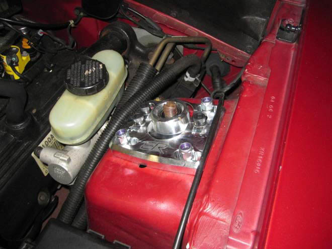
Step 7:
Compress the strut and move it back inside the
strut tower and through the camber plate,
making sure the small end of the strut bushing
mates properly with the bearing in the center of
the plate. It may be necessary to jack up
slightly on the control arm and gently persuade
the strut into place.
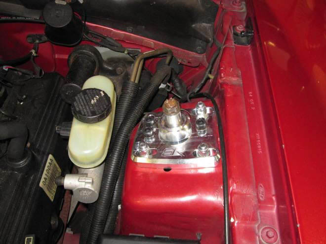
Step 8:
Install the remaining strut bushing over the
threaded end of the strut with the small end
facing down as shown. Make sure the small
end of the bushing slides flush into the bearing
housing. Re-install the large strut nut and
tighten to manufacturers specifications (Factory
Strut Spec is 65-85 ft/lb).
Step 9:
If you are driving the vehicle to have an
alignment performed, adjust the strut to
approximately the same position as before the
install and tighten the 3 stud plate bolts and 3
Allen head bolts to 25-30 ft/lb.
Step 10:
Remove the floor jack from under the control
arm and repeat Steps 2-9 for the opposite side
plate to complete the installation.
Note: Before closing hood, check clearance
between the outer stud plate bolts and the
hood. If necessary, file the bolt slightly to allow
for proper clearance (make sure nut is installed
on stud before filing, drawing it off of the stud
will repair any damaged threads).
Alignment Notes:
An alignment must be performed after
installation of these caster camber plates or you
will experience poor handling and uneven tire
wear. It is highly recommended that the vehicle
be brought to a credible repair shop with the
proper equipment to align the vehicle within
factory (or customized) specifications.
Camber:
To adjust camber, loosen the three 15mm
locking nuts securing the upper plate to the
stud plate and move the upper plate towards
the fender to increase camber (positive
camber), or towards the engine to decrease
camber (negative camber). As a general rule,
the more negative camber, the better cornering
grip a vehicle will have. However, this comes at
the expense of rapidly increased tire wear in
the inside edge of the tire. Conversely, the
more positive camber, the less cornering grip
the vehicle will have. Too much positive
camber can rapidly wear the outside edge of
the tire.
Caster:
To adjust caster, loosen the three Allen head
bolts securing the bearing housing to the upper
plate and move the bearing housing towards
the firewall to increase caster (positive caster),
or towards the front bumper to decrease caster
(negative caster). Most cars will benefit from
an increased amount of positive caster,
however too much positive caster can result in
bumpsteer issues if not addressed properly.
