 FREE 1 to 3-Day Delivery on Orders $149+ Details
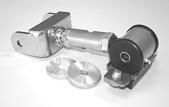
2005-2010 Mustang Steeda Adjustable Street Upper Control Arm Installation Guide
Installation
1. Place the vehicle on a lift or jack stands. The initial installation may be accomplished with the axle on jack stands or in full droop.
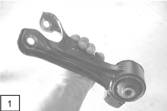
2. Remove the stock upper trailing arm bolts and remove the factory arm. Figure 1 You might have to lower the mounting bracket of the upper arm to remove the bolt on the chassis end. Loosen the two bolts on the bottom side and also the one located under the rear seat, from inside the car. Then pry down on the assembly to remove the bolt.
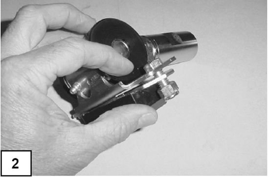
3. Install the bump stop onto the flange of the front mount of the new Steeda arm. Insert the bolts through the flange and through the bump stop with the nut on the urethane side of the bump stop. Figure 2
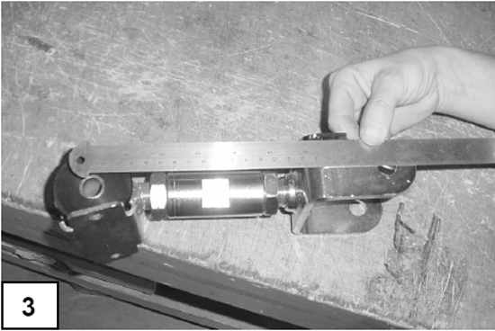
4. Before installing the new trailing control arm you must adjust the length for a beginning setting. The factory upper trailing arm is approximately 215.4 mm (8.48”) between the two mounting locations. For performance use we generally recommend you set the starting length at approximately 212.4 mm (8.36”). Figure 3
5. Grease the outside edges of the bushings with a sticky grease such as synthetic wheel bearing grease or marine grease. Do not skip this step or the bushings may squeak!
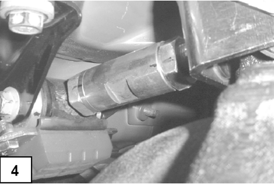
6. Install the new Steeda trailing arm into the factory location with the included thick aluminum spacers on each side of the front urethane bushings. Figure 4
7. Tighten the front and rear trailing arm mounting bolts and torque to factory specs. (129 ft/lbs.) Use the new supplied 14mm nut and washer on the chassis end.
8. Using a standard grease gun, grease the front bushing using a synthetic grease.
9. Before driving your car it is necessary to check the pinion angle. If you adjusted the length as specified in Step 4, you will be very close to the optimum angle. To complete this procedure, the weight of the car must be sitting on the tires, on a level surface. This can be achieved by placing jack stands under the axle tubes and front control arms, or better, on elevated ramps or car lift. Joust the suspension before taking your measurements.
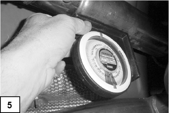
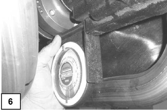
10. Use an analog protractor or digital inclinometer to measure the angle of the front driveshaft (Figure 5). Measure the angle of the pinion flange (Figure 6). Subtract the pinion flange angle from the front driveshaft angle to find the net pinion angle. This procedure is only applicable to the S197 Mustang (2005 ) with the factory two-piece driveshaft. If you are using a slip yoke type gearbox with a one-piece driveshaft, it will be necessary to measure the vertical angle of the transmission mounting surface of the bell housing and then subtract the pinion flange angle to find your net pinion angle. Best angles range from 2o to 5o down.
11. Adjust the new upper trailing arm center sleeve to lengthen or shorten the arm as necessary to correct the pinion angle. One degree of pinion angle change is achieved by rotating the sleeve 1.65 turns. Once you have achieved the desired pinion angle tighten the jam nuts securely against the adjusting sleeve.
12. Re-measure the net pinion angle to insure you have achieved your desired setting and adjust if necessary.
13. Re-check all bolts and make sure everything is secured properly.
14. Take a short test drive and re-inspect the installation before resuming normal driving. If you experience a vibration that was not present before the installation you probably have the pinion angle set incorrectly. Trailing arms should be inspected regularly for safety.
Installation instructions provided by Steeda
Related Guides
-
Installation
-
Installation
-
Installation
