 FREE 1 to 3-Day Delivery on Orders $149+ Details
How To Install Steeda Adjustable Street Rear Upper Control Arms 1979-2004, Excludes 1999-2004 Cobra
Installation Time
3 hours
Tools Required
- Basic socket set
- Large crescent wrenches
- Jack and jack stands
- Drill, 3/8” bit, and 2” wire wheel
- Yard stick
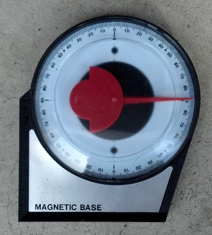
- Magnetic base gravity angle gauge (available at most tool stores for less than ten dollars)
- Blue Locktite
- Extra suspension lubricant
- WD-40
- Brake cleaner
- Rags
Magnetic base gravity angle gauge
Checking Pinion Angle:
1. Raise and support the front of the car with jack stands. Raise and support the rear of the car to the same height as the front with jack stands placed under the rear axle, so that the rear suspension is fully loaded.
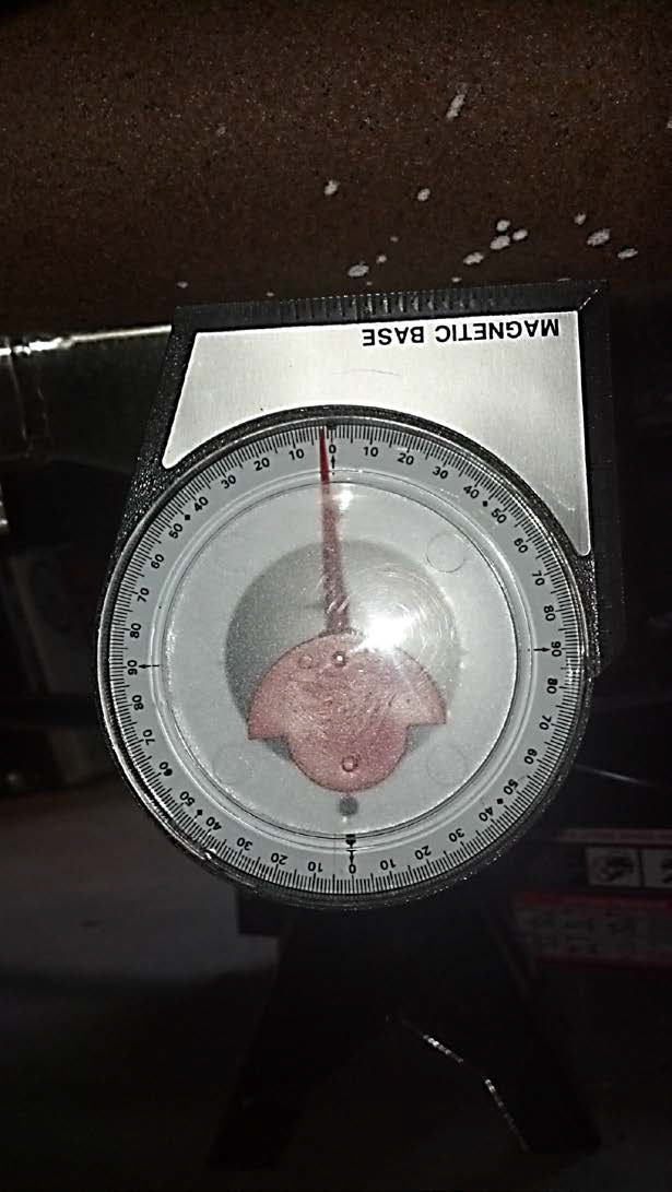
2. Using a magnetic base gravity angle gauge, set the gauge on the bottom of the driveshaft and record the number of degrees from zero the gauge reads. Note whether the angle is to the left or right of zero.
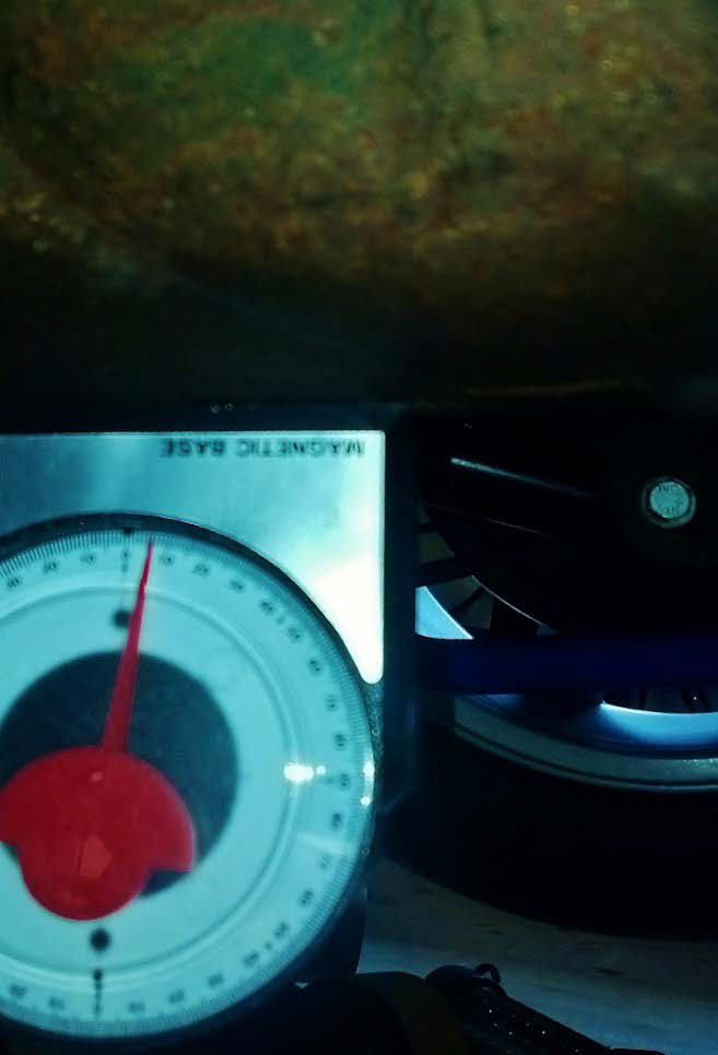
3. Set the gravity angle gauge on the flattest portion of the bottom of the differential housing, and again record how many degrees from zero the gauge reads. Note if the angle is to the left or right of zero.
4. Use the two recorded values to determine the pinion angle, which is the number of degrees between the angle of the driveshaft and the angle of the differential. With this car, the driveshaft had an angle of 2 degrees with the angle to the left of zero, meaning the front of the driveshaft was higher than the rear. The differential had an angle of 4 degrees with the angle to the right of zero, indicating that the front of the differential is lower than the rear. Since the angles of the driveshaft and differential are on opposite sides of zero, the angles are added, yielding a pinion angle for this car of 6 degrees nose down. To bring the front of the differential up and reduce the pinion angle, the upper control arms should be extended. For a differential that is nose up, shorten the upper control arms to bring the pinion down. The recommended pinion angle is 3-4 degrees nose down. A 1/8” change in length of the control arm will roughly result in a 1-2 degree change of pinion angle. Note: nose down is more common in lowered cars, while very little pinion angle should be expected when working on a car with factory spec suspension.
Removal:
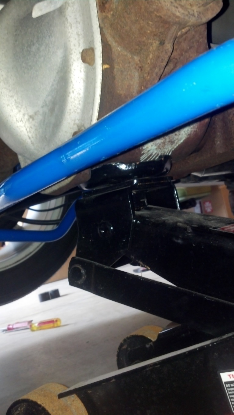
1. Begin by supporting the vehicles on jack stands placed under the rear sub-frame.
2. Load the rear suspension slightly by raising the differential with a jack.
3. Work on one side at the time. Remove the nut from the bolt that connects the upper control arm to the rear axle. Wiggle the bolt out, using the jack to manipulate the height and angle of the axle so the bolt slides out easier.
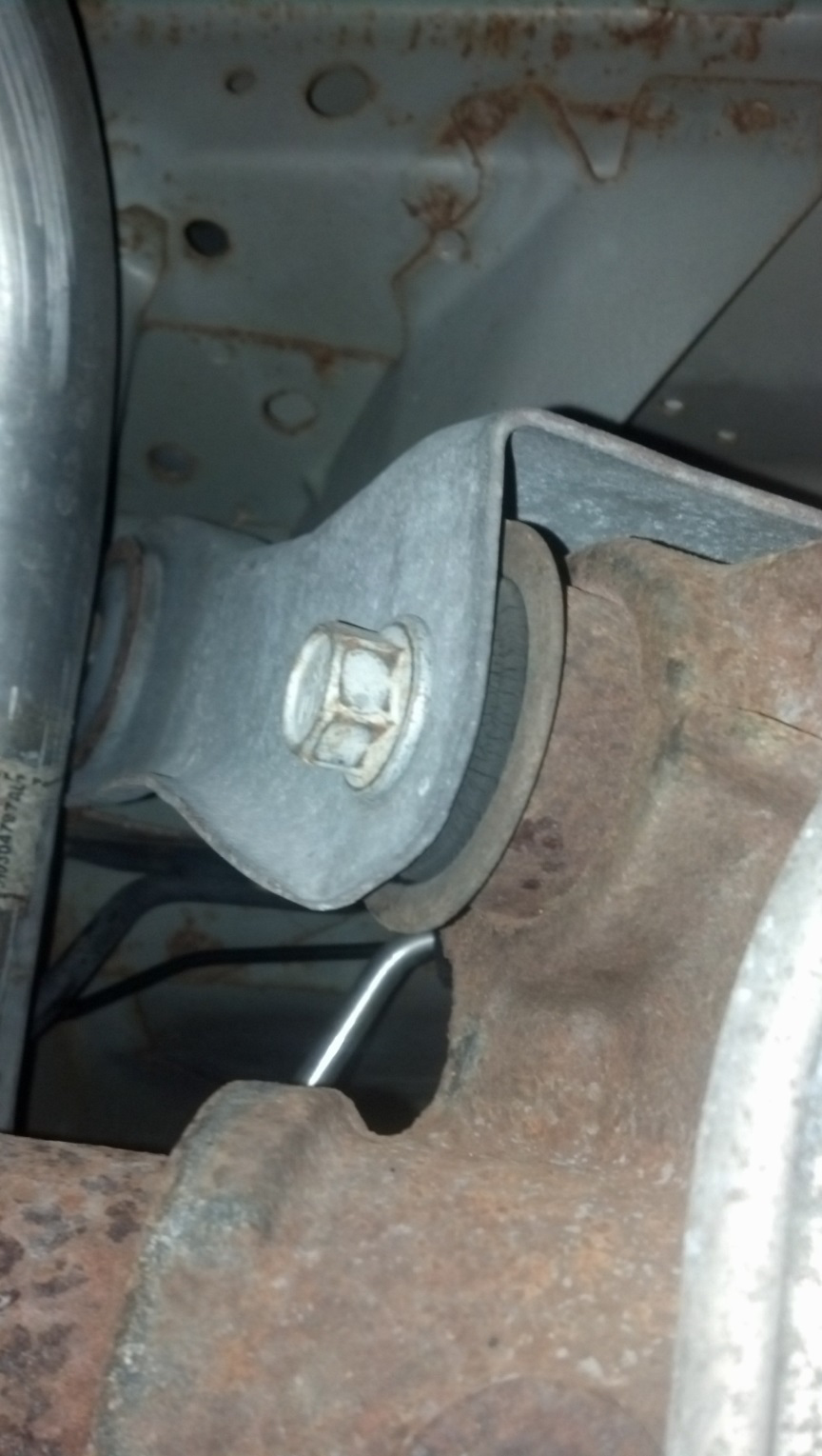
4. Pivot the upper control arm up from the axle, and remove the nut and bolt attaching the upper control arm to the chassis. Remove the control arm from the car.
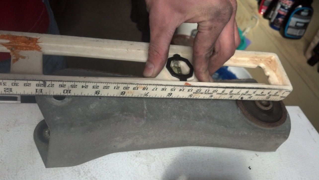
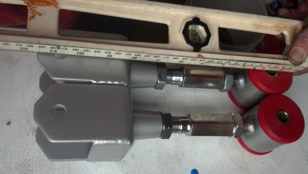
5. Using your preferred method, measure the distance between the bolt holes on the factory upper control arm. This 2002 GT’s UCA was right at 9.25”. Note: when using a yard stick as pictured, put the 1” mark at the front of the chassis end’s hole, and measure to the front of the axle end’s hole. Remember to subtract 1” from the measurement.
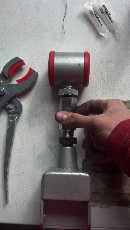
6. Prepare the Steeda upper control arms by adjusting the lengths of both control arms to the factory length you recorded. Get an initial measurement, and start by setting the upper control arm on a flat surface. Rotate the center section to extend both ends from the center evenly. Do this to both Steeda upper control arms and be sure that they are the same length. With the upper control arms at the appropriate length, snug the jam nuts to the adjustable center section of the control arms. Noting that the pinion angle on this car was 6 degrees nose down, I went ahead and added an extra 3/16” to both control arms to get them to 9 716”. This is not required; however, since I knew the pinion needed to come up roughly 3 degrees, I got a head start and lengthened them what roughly translates into 3 degrees.
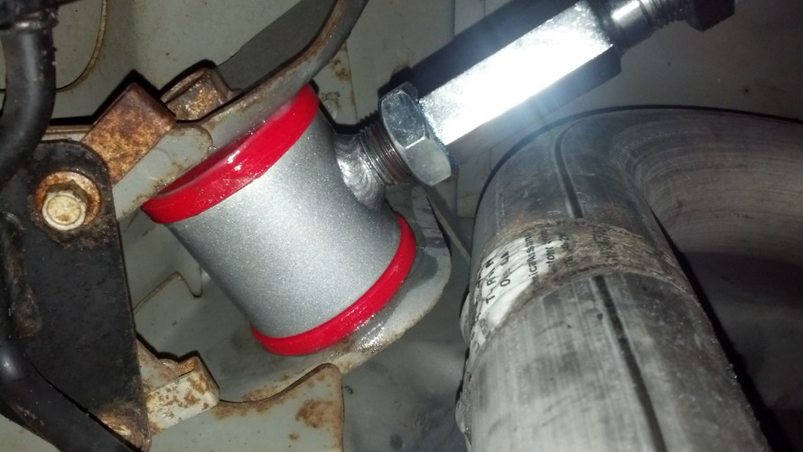
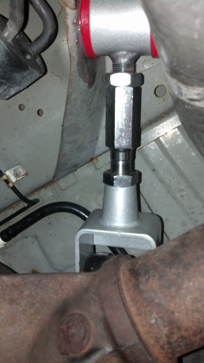
7. Now remove the upper axle bushing using a drill and your preferred bit size, a 3/8” bit works well. This is the most difficult part of this installation and is time consuming. Be sure to stay patient as doing this correctly without distorting/damaging the sleeve will take some time. Note: Maximum Motorsports’ “Rear Upper Control Arm Bushing Tool” will not work for this project. This tool is designed to press out the upper axle bushing housing with the bushing still inside. This Steeda kit requires the factory bushing housing to stay in place with only the bushing removed, as the kit comes with a high quality replacement upper axle bushing and no replacement sleeve.
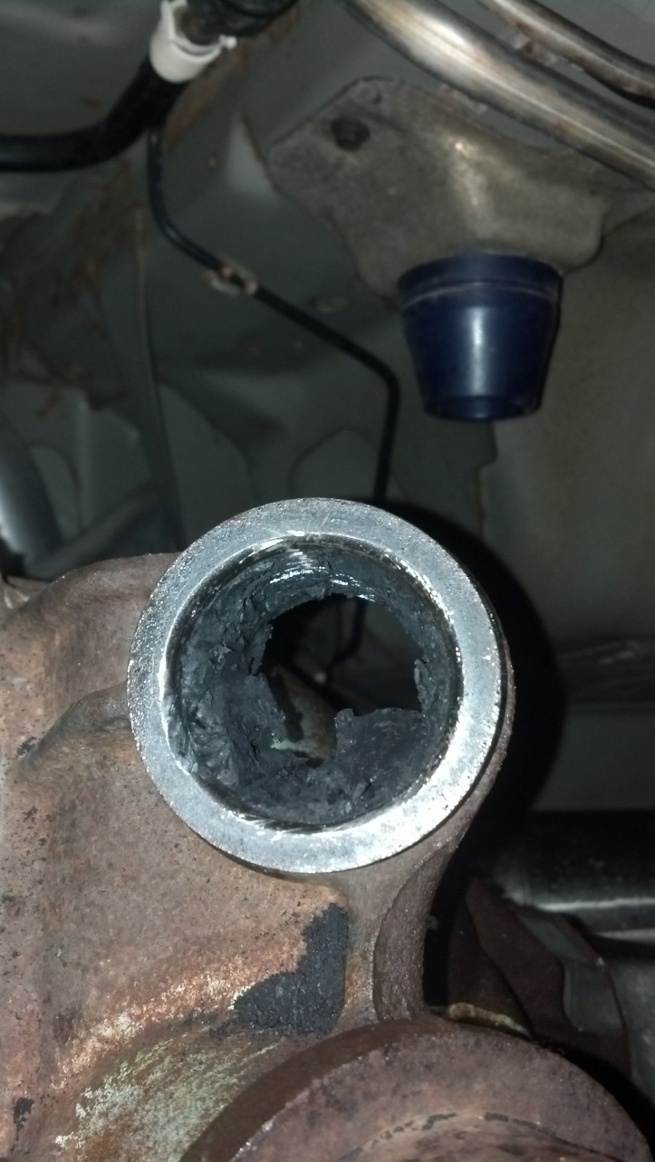
8. Once I got to this point, I found that using a 2” wire wheel worked much quicker and cleaner. I had to slightly modify the new 2” wire wheel using some large pliers to reduce the length of the wires by clamping them down (this is necessary as the bushing’s housing is slightly smaller than 2” in diameter). I also sprayed a little WD-40 as I drilled to make this job easier.
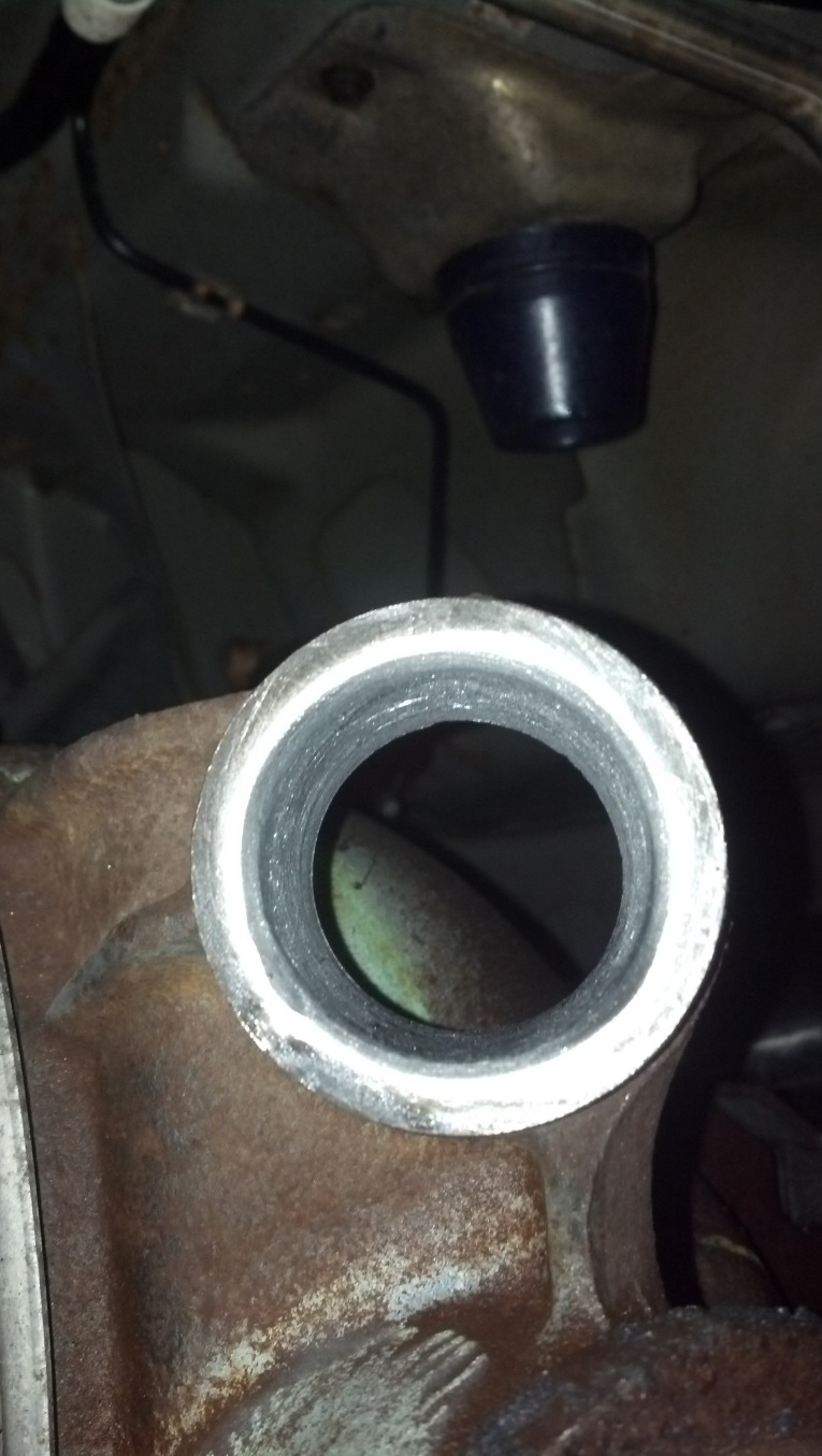
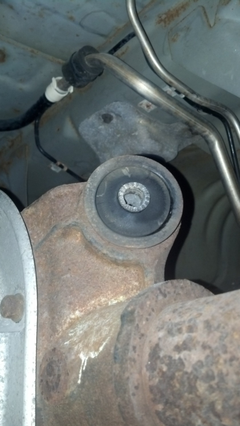
9. With the old bushing finally out, use some brake cleaner to spray the differential and the upper axle bushing housing out thoroughly.
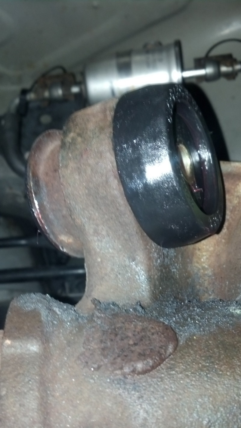
10. Using the supplied suspension grease, liberally grease the bushing, thrust washer, steel sleeve, and bushing housing. Press the upper axle bushing into the housing with the bushing’s flange facing the rear of the car. Tapping it with a mallet with ensure a solid fit. Note: have some extra suspension grease on hand. The better the bushings are greased the less likely the bushings will suffer from pre-mature wear and this will ensure the bushings do not squeak.
11. Press the sleeve into the center of the bushing. Then put the thrust washer on the other end of the bushing housing, on the pinion side of the differential. Make sure the numbers are facing towards the front of the car.
12. Now grease the red bushings on the upper control arm, as well as the contact area in the upper control arm torque box. Bolt the upper control arm up first to the chassis side, then on the axle end.
13. Repeat steps 3-4, 7-12 for the other side.
14. With both new upper control arms installed, tighten all the hardware mounting the upper control arms to the chassis and axle.
15. Repeat the procedure for checking pinion angle. Now determine whether the upper control arms need to be lengthened or shortened. If they are the correct length, back off both jam nuts and apply blue Locktite where the jam nuts are snugged. Then tighten up the jam nuts taking care not to move the center adjustment.
16. If the control arms are not the correct length, mark a line down the center of the underside of both of the upper control arm’s center adjustments sections. Back the jam nuts off and lengthen or shorten the control arms in full or half turn increments. Note: it is vital that the control arms are the same length. Do the exact same number of revolutions to both of the upper control arms, using the center line as a reference.
17. After each adjustment, use the procedure for checking pinion angle. This can be time consuming, however, this is very important to get right and is worth the time.
18. Once the desired pinion angle is achieved (3-4 degrees nose down), apply blue thread locker to both sides of the center adjustment section and snug the jam nuts up on both sides of the center adjustment.
Enjoy harder launches and improved cornering.
Installation Instructions written by AmericanMuscle Customer John Collman 9.3.2014
