FREE 1 to 3-Day Delivery on Orders $149+ Details
How to install Steeda Adjustable Street Rear Upper Control Arms on your 1979-2004 Mustang
Installation
Note: Check your pinion angle before you start, so that you know which way to adjust the new arms. But beware that if the upper and lower control arm bushings are worn out, the axle may shift when the car is driven, making your measurements less accurate.
1. Raise the vehicle and place it on jack stands with the rear axle hanging. (no weight on the rear axle.) Place a jack under the differential housing and support it lightly.
2. Unbolt and remove one upper rear control arm using an 18mm wrench. Remove only one control arm at a time. This will make it easier to line up the new control arms when they are installed.
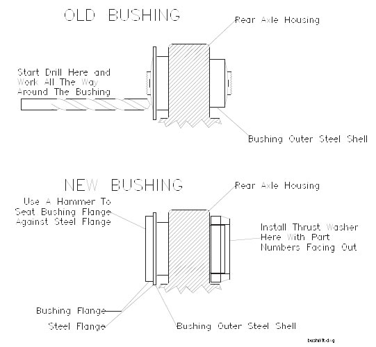
3. Remove the rubber from inside the bushing shell on the rear axle housing. IMPORTANT Do Not remove the outer steel shell from the axle housing. You will need it to hold the new bushings. The best way to remove the rubber is to drill it out with a 3/8” drill bit. Drill into the rubber at the outer edge, next to the outer steel shell. Drill all the way through the rubber with the drill bit rubbing against the steel shell. Let the twisting drill bit walk all the way around the outer edge of the bushing and separate it from the steel shell. Pull the rubber out.
4. Clean the inside of the shell and remove any old rubber with a wire brush or "Scotchbrite" pad.
5. Adjust the length of the control arms as needed to achieve the desired pinion angle. 3 to 4 degrees nose-down is recommended. Shorten the arms for more nose-down pinion angle.. Lengthen the arms to bring the pinion angle up. 1/8 inch adjustment will change the pinion angle approximately 1 to 2 degrees. Adjust both arms at the same time to be sure they are the same length.
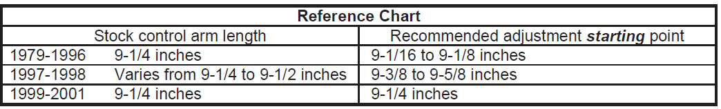
WARNING: DO NOT INSTALL THE CONTROL ARM WITH A LENGTH (center to center of the bolt holes) LONGER THAN 9.63 inches for P/N 555-4100 (with bushing end) or 9.45 inches for P/N 555-4101 (with rod end). ALWAYS CHECK TO MAKE SURE THERE IS AT LEAST 11/16" OF THREAD ENGAGED ON BOTH SIDES OF THE ADJUSTER. SHORTENING THE CONTROL ARMS MORE THAN 1/2" FROM STOCK CAN CREATE NOISE, VIBRATION AND HANDLING PROBLEMS. FAILURE TO HEED THESE WARNINGS MAY LEAD TO SERIOUS INJURY.
6. Tighten the jam nuts on the control arms. Loctite thread locking compound is recommended.
7. Remove the steel sleeve from the center of the new axle bushing (if already installed). Lightly grease the inside of the shell and press the bushing into the shell with the bushing flange facing out. After the bushing is installed, grease the steel sleeve and tap it into the bushing with a hammer.
8. Slip the thrust washer (the large black urethane ring) over the small end of the axle bushing with the part numbers facing away from the bushing (# should face towards the center of the car). See diagram.
9. Grease the sides of the bushings and the thrust washer with a sticky grease and install the front end of the control arm into the car. Do not tighten the bolt yet.
10. Pull the control arm down over the axle bushing and install the bolt. Raise or lower the front of the differential with a jack to align the bolt holes. In some cases it may be necessary to jack under the rear of the differential (under the cover) to tilt the bushings forward.
11. Tighten both bolts and repeat the procedure for the other arm.
12. Check the pinion angle using the accompanying instruction sheet. Because of production variances and the large variety of modified cars, some re-adjustment may be necessary.
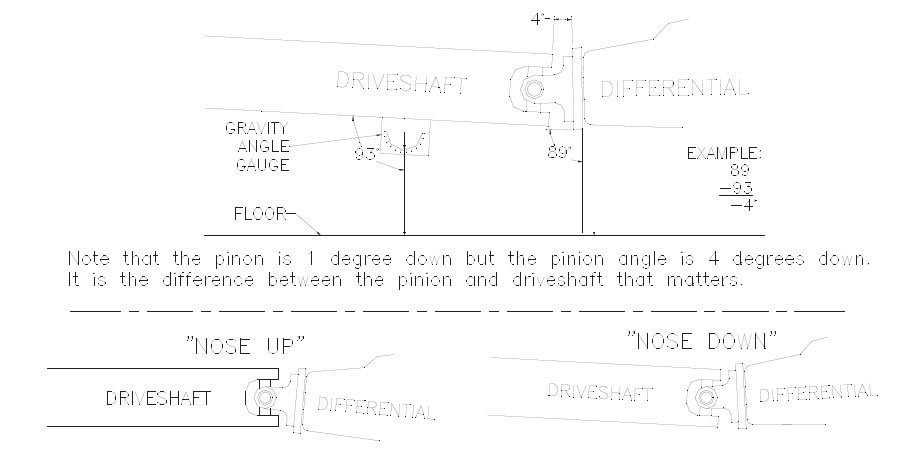
Measuring Pinion Angle:
Pinion angle is the difference between the centerline of the driveshaft and the centerline of the pinion shaft of the differential. To measure it you must be able to work under the car with the suspension fully loaded and the car level. A drive on lift works best for this.
Method "A" - (recommended)
Use an angle measuring gauge (adjustable protractor) to measure the difference between the pinion flange and the drive shaft directly. These gauges are available for under $10 from a hardware store. Place the edge of the gauge vertically against the front of the pinion flange, beside the driveshaft. Extend the measuring arm forward parallel to the bottom of the driveshaft. Extend a straight edge under the driveshaft to the measuring arm of the angle gauge. Hold the straight edge flat against the bottom of the driveshaft and adjust the measuring arm to read the angle. Depending on the gauge you use, you may have to subtract 90° from your reading to get the correct number. Your final measurement should be between 0 and 5. Examine the diagram at the bottom to determine if the pinion angle is nose up or nose down.
Method "B"
1. Use a gravity angle gauge (Available at hardware stores) to measure the angle between the driveshaft and the ground. Hold the gauge on the bottom of the driveshaft. Align the gauge front-to-back under the car in line with the driveshaft and read the number from the gauge. Write down this number.
2. Next, hold the side of the gauge against the front of the pinion flange (beside the driveshaft). Measure the angle between the pinion shaft and the ground. Write down this number.
3. Subtract the first number from the second number. This is your pinion angle. Examine the diagram at the bottom to determine if the pinion angle is nose up or nose down.