FREE 1 to 3-Day Delivery on Orders $149+ Details
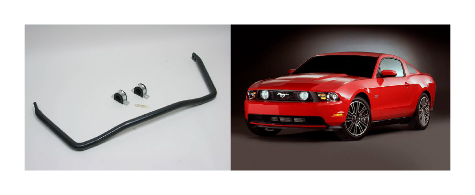
How to Install ST Suspension Anti Sway Bar Kit - Coupe & Convertible on your Mustang
Installation Time
2 hours
Tools Required
- Blocks and Wheel chocks
- Ratcheting Socket Wrench (5.5, 15 and 18mm)
- Safety Glasses
- Floor jack and Jack Stands
- Properly rated floor jacks and support stands
- Combination Wrench (15 and 18mm)
- Torque wrench: 0-100 lb ft. range
CONGRATULATIONS! You were selective enough to choose a SUSPENSION TECHNIQUES PRODUCT. We have spent many hours developing our line of products so that you will receive maximum performance with minimum dif-
Note: Confirm that all of the hardware listed in the parts list is in the kit. DO NOT begin this installation if any part is missing. Read the instructions thoroughly before beginning this installation.
Warning: DO NOT work under a vehicle supported by only a jack. Place support stands securely under the vehicle in the manufacturer’s specified locations unless otherwise instructed.
Warning: DO NOT drive the vehicle until all work has been completed and checked. Torque all hard ware to values specified. Reminder: Proper use of safety equipment and eye/face/hand protection is absolutely necessary when using these tools to perform procedures!
Note: It is very helpful to have an assistant available during the installation process.
Note: We DO NOT RECOMMEND using wheel ramps while performing this installation.
KIT INSTALLATION
1 VEHICLE PREPERATION
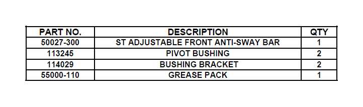
1a. Open the hardware kit and remove all of the contents. Refer to the parts list to verify that all parts are present.
1b. Park the vehicle on a smooth, level concrete or seasoned asphalt surface and activate the parking brake. Block the REAR wheels of the vehicle with appropriate wheel chocks; making sure the vehicle’s transmission is in 1st gear (manual) or “Park” (automatic).
1c. Using a properly rated floor jack, lift the FRONT wheels of the vehicle off the ground. Place sup- port stands, rated for the vehicle’s weight and in the factory specified locations. Refer to the vehicle Owner’s Manual. Prior to lowering the vehicle onto the stands, make sure the supports
will securely contact the chassis.
1d. It is very important that the vehicle is properly supported during this installation to prevent personal injury and chassis damage. Make sure that the support stands are properly placed prior to performing the following procedures. We DO NOT RECOMMEND using wheel ramps while performing this installation.
1e. Slowly lower the vehicle onto the stands and, before placing the vehicle’s entire weight on them, again check that they properly and securely contact the chassis as described above. Check for possible interference with any lines, wires, cables, or other easily damaged components.
2. REMOVING THE ORIGINAL EQUIPMENT ANTI-SWAY BAR
2a. Use a 5.5mm socket to remove 4 bolts securing the central front undertray. Remove the undertray.
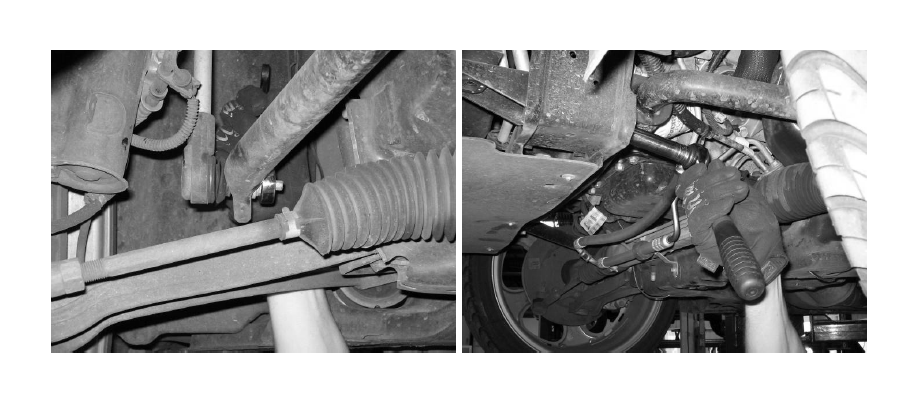
2b. Located at the end of the end-links connected to each end of the original equipment anti-sway bar (ASB). Using a 15mm socket and tool remove the mounting nut securing the lower end-link to the ASB. It might be necessary to use a 8mm socket on the end of the end-link stud to pre vent it from spinning. Temporarily leave the end-link studs connect to the ASB so that the bar can hang on the end-links.
2c. Using a 15mm socket, remove the nuts securing the OEM bushing brackets located behind the radiator.
2d. Remove the original equipment ASB and bushings.
3. INSTALLING THE ANTI-SWAY BAR
3a. Using the supplied polyurethane grease pack, lubricate the insides of the two new bushings where they touch the ASB. Spread and clip the new bushings over the Suspension Techniques Adjustable Front ASB in the same areas as they were located on the original equipment ASB.
3b. Once the new bushing/brackets have been located on the new Anti-Sway Bar, hang both ends of the new ASB up by the end links.
3c. Pivot the new ASB into position and secure each bushing/brackets up to their respective mounts .
3d. Finger-tighten the OEM nuts and secure the ASB to the frame.
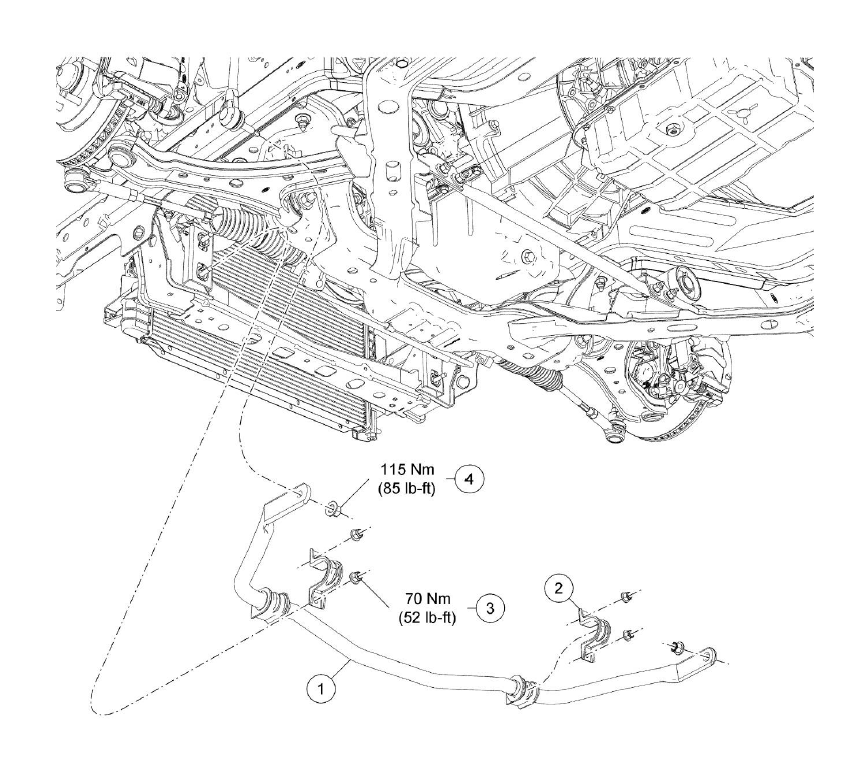
3e. Using the OEM nuts and a 18mm and 8mm tool, secure the end-link studs to the new ASB with 85 lb•ft (115 Nm) of torque.
3f. Using a 15mm tool, tighten all four OEM nuts for the bushing brackets and tighten to 52 lb•ft (70 Nm).
3g. Install the OEM center splash/ under tray using the OEM bolts.
5. FINALIZING THE INSTALLATION
5a. All hardware being fastened to the vehicle’s original fastening points should be torqued to the proper specifications. To prevent chassis damage, never over-torque the hardware.
5b. Check that all components and fasteners have been properly installed, tightened and torqued.
5c. Check brake hoses and other components for any possible interference.
5d. Lift the vehicle and remove the support stands. Carefully lower the vehicle to the ground.
5e. Immediately test-drive the vehicle in a remote location so that you can become accustomed to the revised driving characteristics and handling. Be aware that the vehicle will handle substantially different now that it has been modified. 5f. Installation is complete. Check all of the hardware and re-torque at intervals for the first 10, 100, 1000 miles.
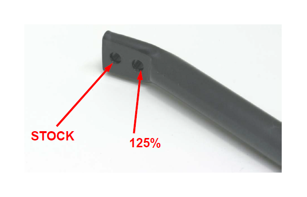
6. SETUP
The Suspension Techniques Adjustable Anti-Sway bar can be tuned for the desired roll resistance by connecting the anti-sway bar end-links to different attachment points on the bar. Each side of the bar has two different attachment points. Attaching the end-links to the holes furthest out on the bar tab will be the softest roll setting while attaching to the holes closer in will increase roll stiffness. Increasing the front roll stiffness will typically increase understeer. Below are the percentage increases in torsional stiffness over the stock bar for each end-link position.