 FREE 1 to 3-Day Delivery on Orders $149+ Details
How to Install a Steeda X2 Ball Joint Kit on Your 1994-2004 Mustang
Installation Time
4 hours
Tools Required
- Floor Jack
- Two Jack Stands
- Ratchet
- 15/16" Socket
- 13/16" Socket
- 15mm Socket or Wrench
- 6mm Socket (preferably a six point socket but a twelve point socket will suffice)
- Large adjustable wrench or 13/16” and 15/16” wrenches
- 4 Bricks or Wheel Chocks
- Lug Wrench
- String or Zip Ties
- Cheater Bar
- Portable Torch
- Pickle Forks
- Hammer
- Ford Suspension Grease Tube
- Grease Gun
- Ball Joint Press Tool Kit (can be rented from local auto parts dealer)
- Thread Locker (not absolutely necessary but suggested)
Removal Procedure:
1. Engage emergency brake and put transmission in gear, (automatics use Park).
2. Using the lug wrench, loosen the five lugs nuts on each of the front wheels. Place bricks or wheel chocks in front of and behind each of the rear wheels.
3. Carefully raise car onto jack stands with floor jack. Once vehicle is secured on jack stands, proceed to finish removing lug nuts and remove front wheels from car.
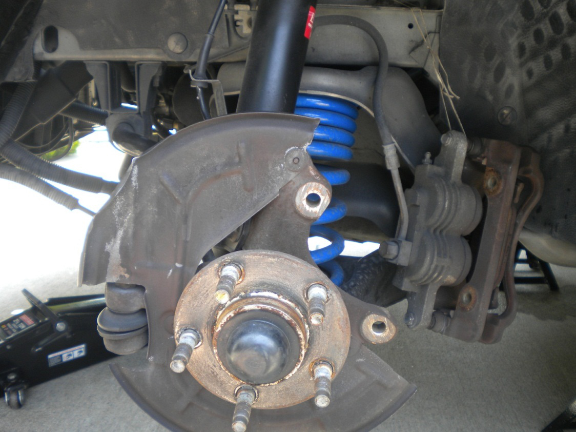
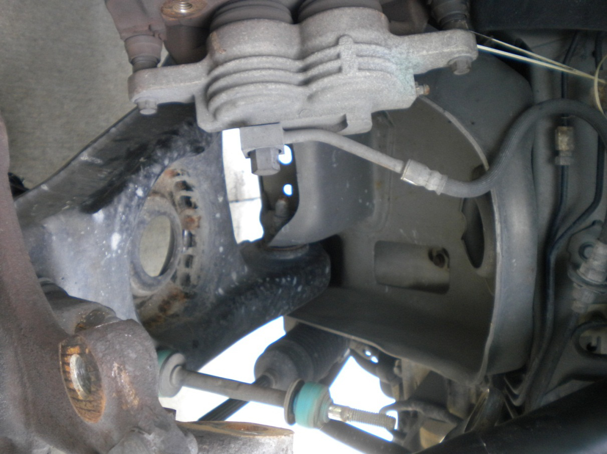
4. Locate and remove the (2) 15mm bolts that hold the brake caliper to the spindle. Then remove the brake caliper from the rotor and tie it up out of the way with the string or a zip tie.
5. Pull the rotor off the spindle.
6. Starting on one side, move floor jack under lower control arm and slightly lift the control arm only to put a slight load on it.
7. Locate the sway bar end link and remove the 15mm top nut using the 15mm deep well socket.
8. Using the 15/16” socket, remove the nut holding the brake line bracket to the bottom of the strut, where it bolts to the spindle. Move the bracket towards the front of the car so it is out of the way in order to have clear access to the (2) 15/16” nuts holding the bottom of the strut to the spindle.
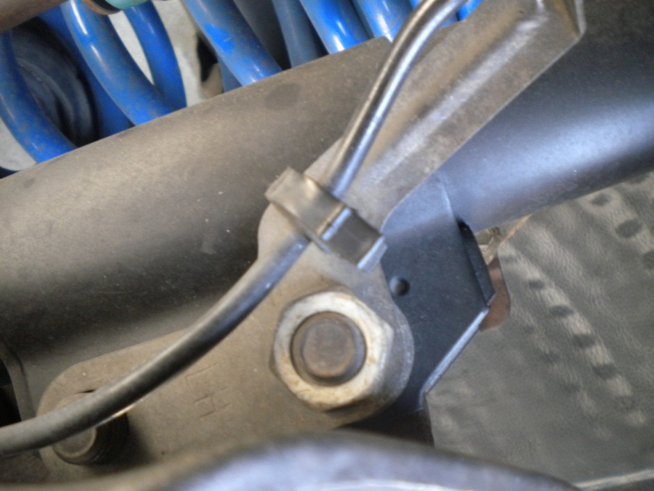
9. Remove the (2) 15/16” nuts while holding the 13/16” bolt each nut is attached to.
10. With the bottom of the strut disconnected from the spindle, orient the strut towards the front of the car.
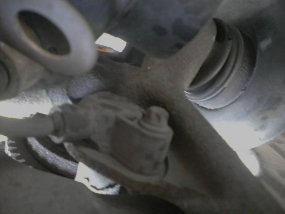
11. Find the ABS sensor located on the lower portion on the back of the spindle and remove the six point bolt using the 6mm socket. Make sure the proper socket is used to remove this bolt so that it is not striped and may be reused. Move this toward the front of the car out of the way.
12. Remove the spring. I find it easier to pull the bottom of the spring out while using my knee to press down the control arm to create more room for the spring to come out. The use of a spring compressor may be used but is certainly not necessary. If found to be too difficult, using a pry bar of some sort may help to get the spring free.
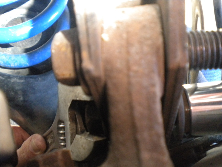
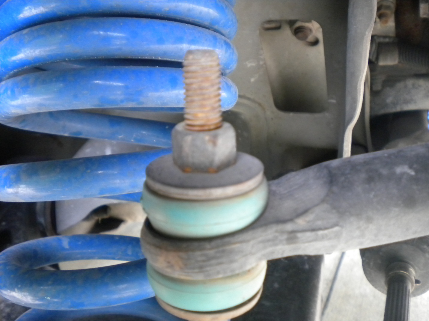
13. Now that everything is disconnected from the spindle except for the lower ball joint and the tie rod end, locate the 15/16” ball joint top nut and remove it. Note that this nut is very tight and will require a great deal of strength to remove. The use of a cheater bar or another sort of extension to put on the end of the ratchet will make it easier to remove the top nut.
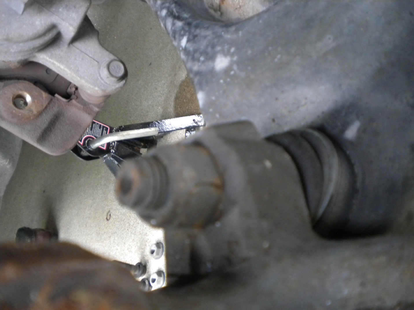
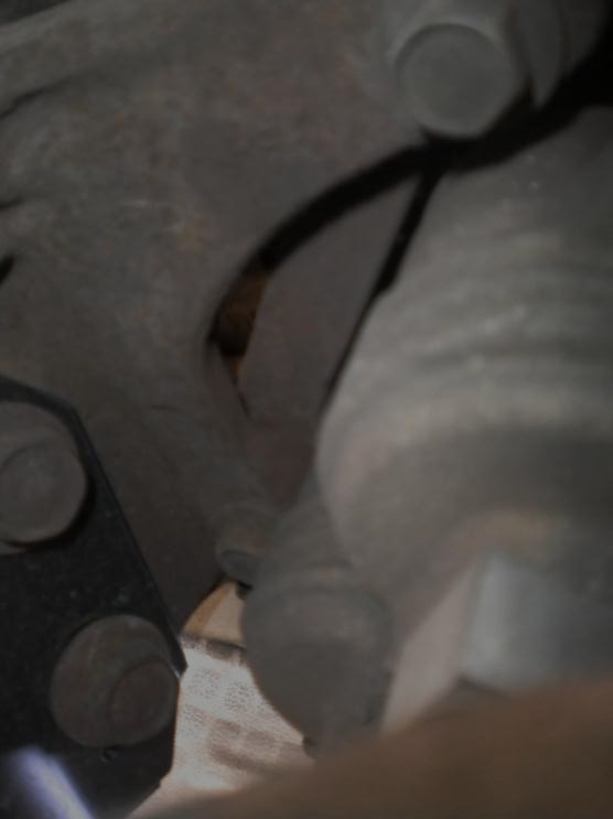
14. Once the top nut has been removed, it is now time to free the spindle from the ball joint. This is the most difficult part of the entire removal procedure. The quickest and easiest way to complete this task is to use the portable torch to heat up the ball joint, the portion of the ball joint that is under the spindle and above the control arm (avoid putting the hottest part of the flame directly on the control arm or spindle so that these materials are not weakened by the heat). Once this is heated for around twenty seconds, immediately take the pickle fork and put it between the spindle and control arm (the same area that was just heated). Use the hammer to beat the pickle fork. This will help to free the spindle from the ball joint. If this does not work on the first try, do not lose hope. Simply repeat this process as many times necessary until the spindle finally pops up. Once the spindle is freed, move it off the ball joint and rotate it to the front of the car.
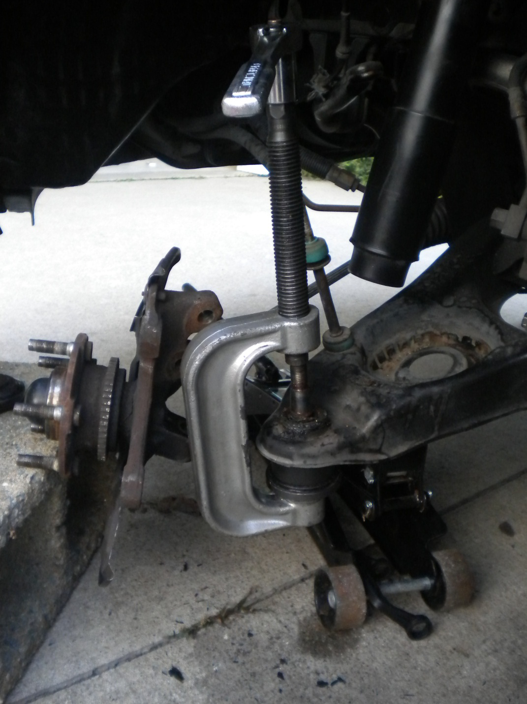
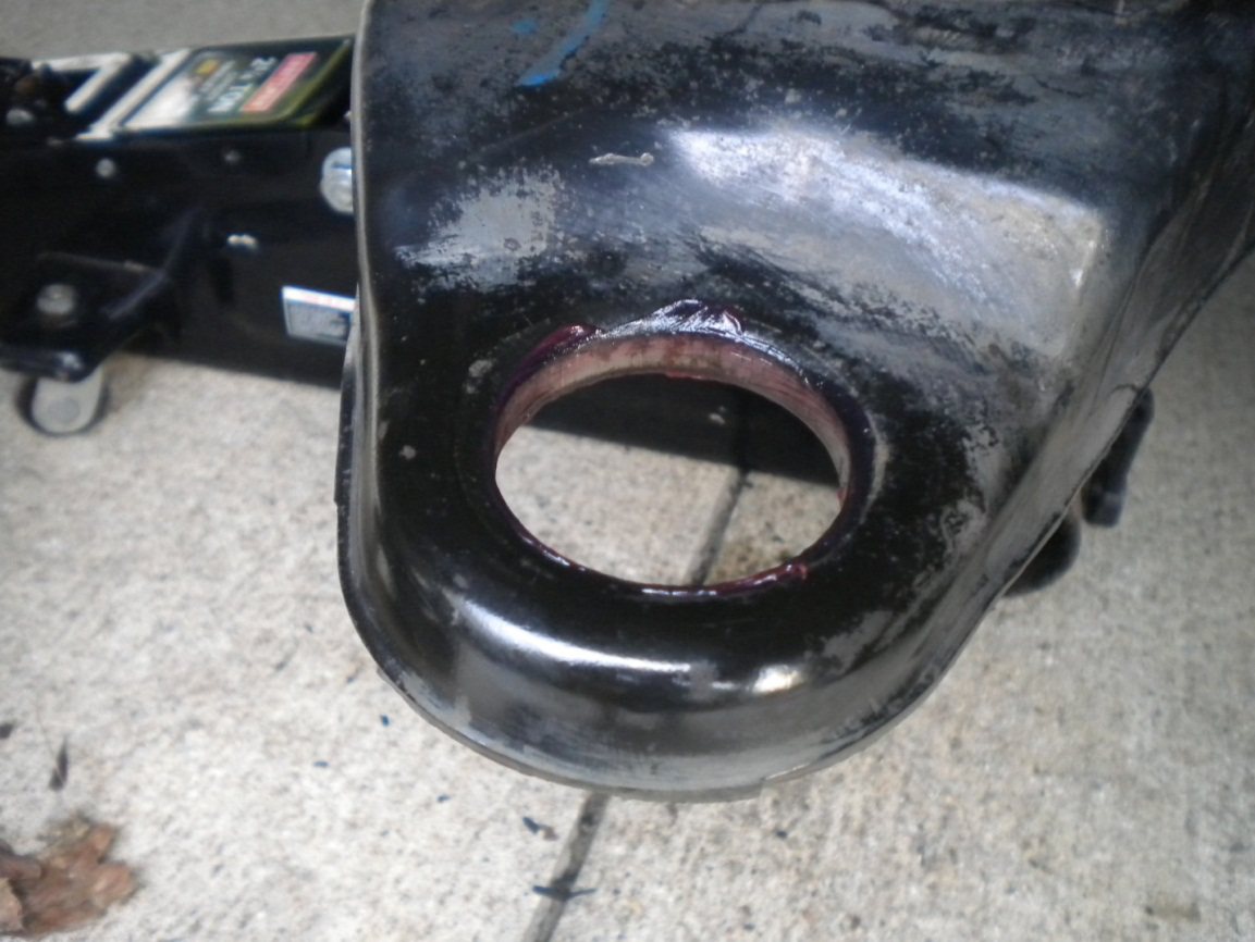
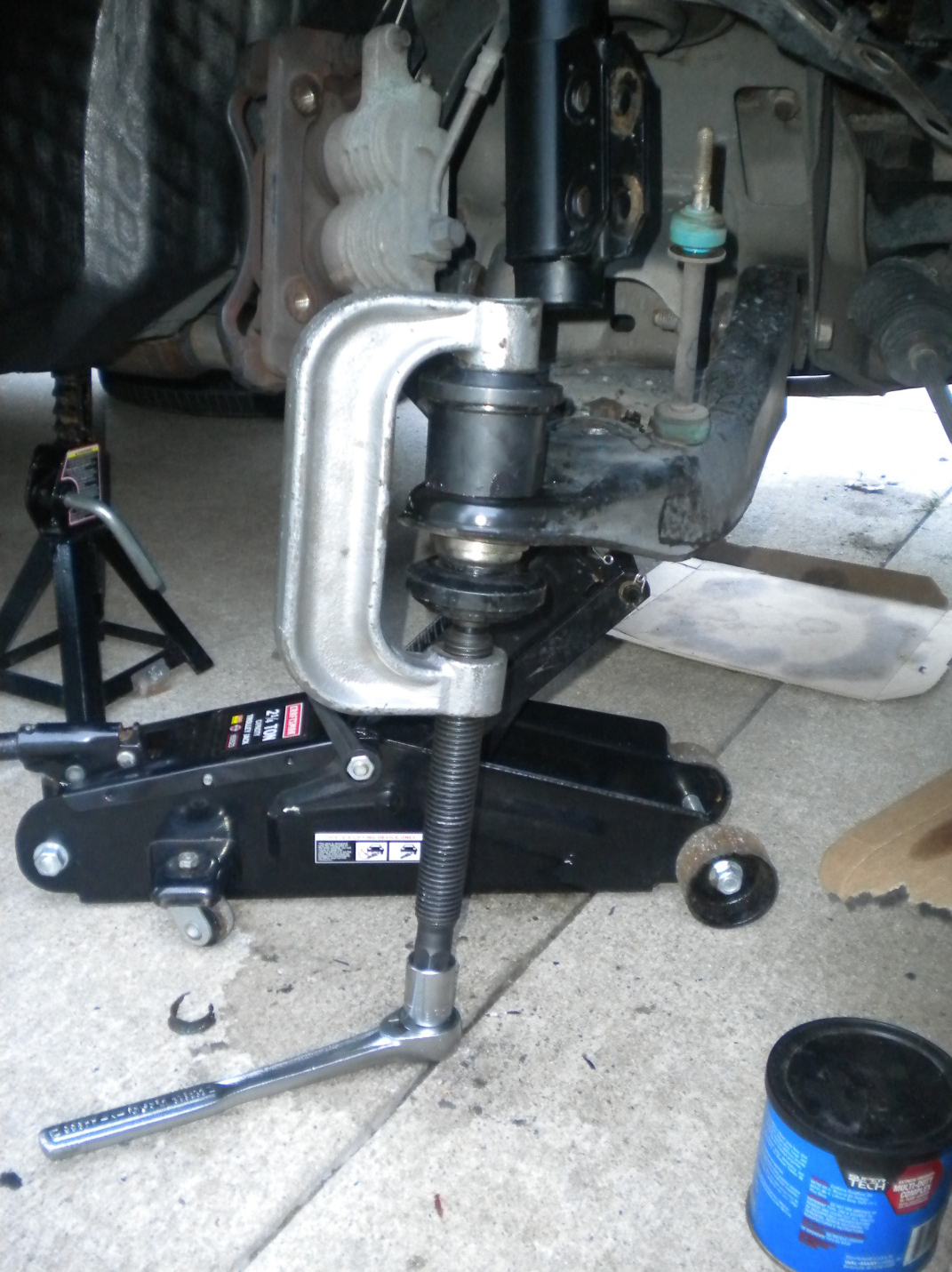
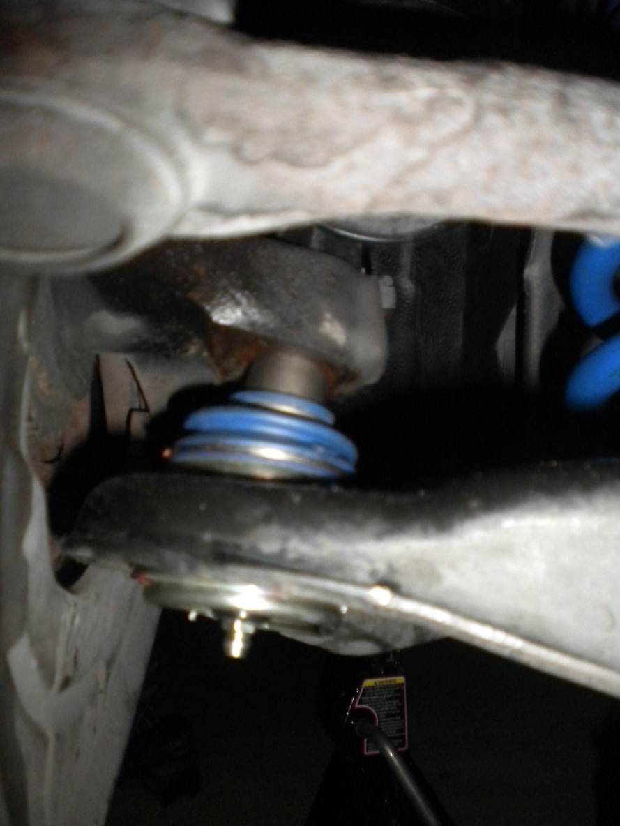
15. It is now time to press the ball joint out of the control arm. Follow the directions on the ball joint removal tool. This process is pretty straight forward, however, once a few turns have been completed with the ratchet, it will become hard to turn and the cheater bar will become useful again. After about a dozen turns, the ball joints should start to move down out of the control arm. Keep going until the ball joint is completely out.
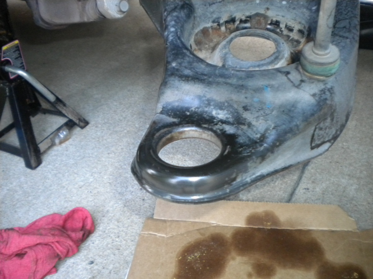
16. With the old ball joint now finally out, grease the control arm where the new ball joint will go in.
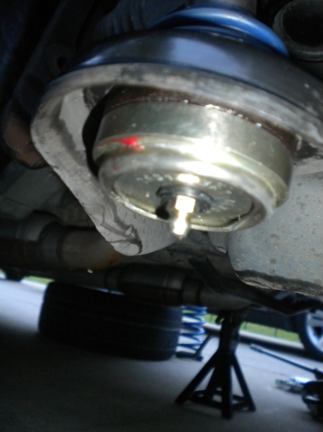
17. Now the new ball joint must be pressed into the control arm. Along with greasing the control arm, another helpful tip that I found to work well was to place the new ball joints in the freezer several hours prior to the installation. This will actually make them shrink and go in the control arm slightly easier. Using the ball joint tool nearly the opposite of the removal, press the new ball joints in from the bottom of the control arm using the more specific directions provided by the tool’s manufacturer.
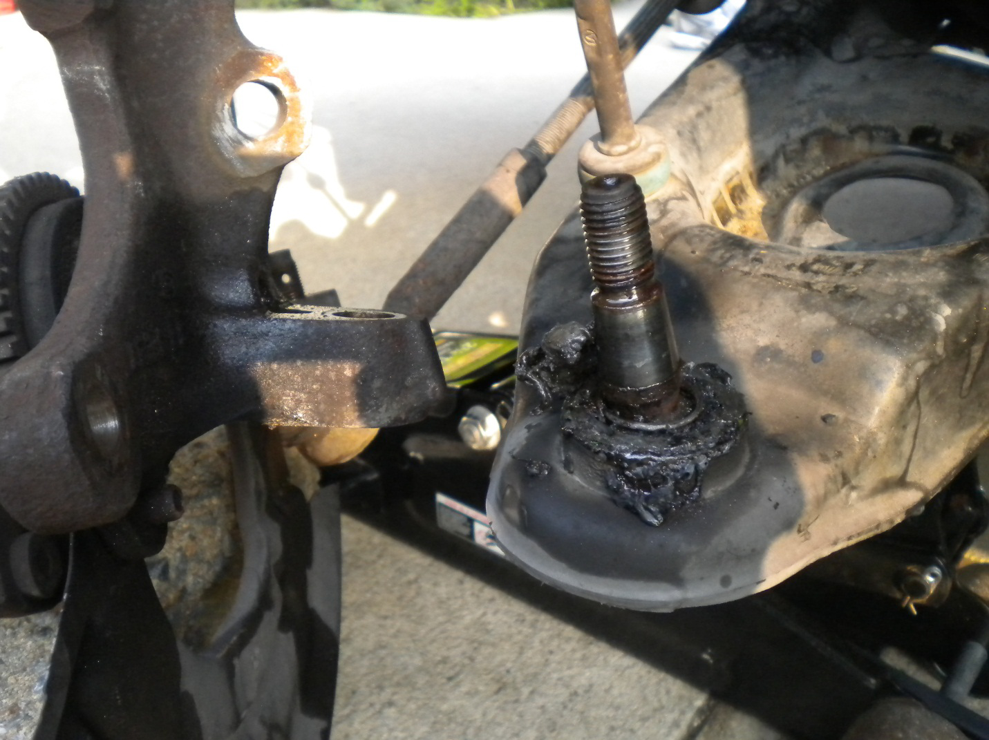
18. With the new Steeda ball joint pressed into the control arm, install the grease fitting on the bottom side of the ball joint. Only snug this fitting on the ball joint, do not over tighten. Once snugged, use the grease gun to pump the ball joint full of grease. The ball joint is completely greased once grease flows from the exterior of the boot. Wipe off excess grease.
Installation Procedure:
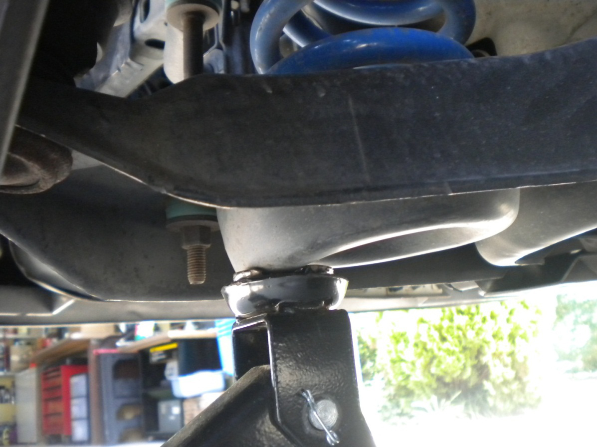
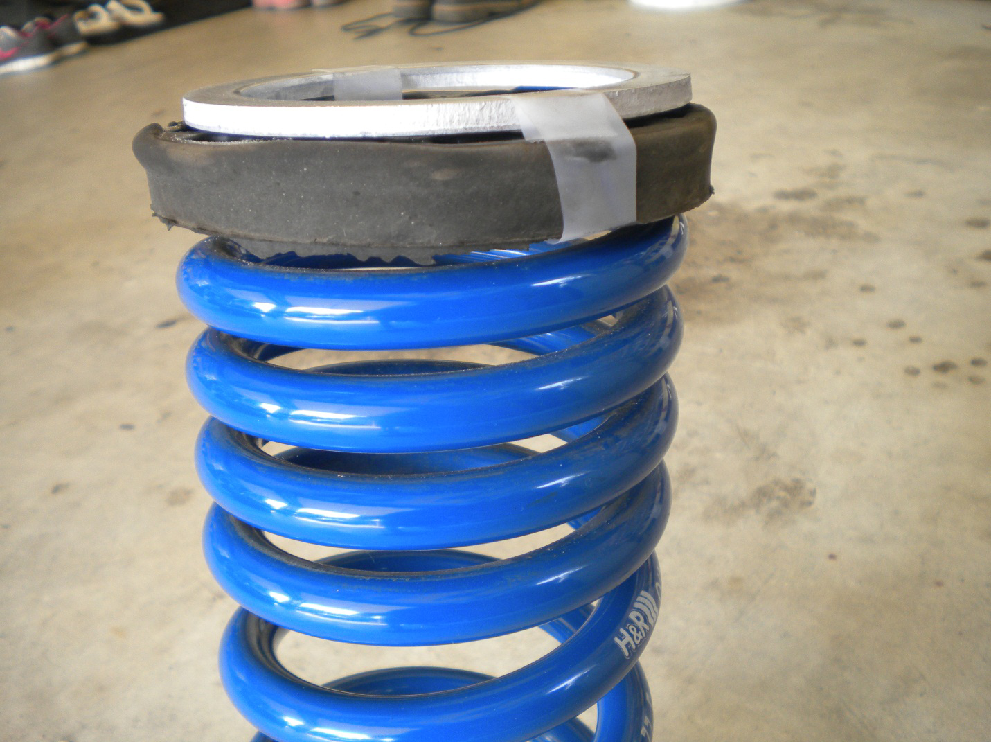
19. If your vehicle is lowered more than one and a half inch, the silver spacers provided in the ball joint kit must be used to correct your steering geometry. If your vehicle is equipped with the factory springs or is only lowered slightly, the silver spacers do not have to be installed if another half inch drop of the front suspension is desired. If the vehicle is to be returned to factor ride high, use the silver spacers. Since my vehicle is lowered with H and R super sport springs, I used the spacers. With the spring installation being hard enough without having to worry about adding a spacer, I found it to be easier to tape the spacer to the top of the insulator before attempting to install the spring. To install the spring, push down on the control arm with your knee, place the top of the spring into the spring perch, and coax the bottom of the spring into its place.
20. Now place the spindle on the new ball joint. I recommend using a small amount of thread locker on the ball joint stud before putting the nut on. This is not absolutely necessary; however, I find it to be cheap insurance. Now tighten the top nut with the 15/16” socket. The ball joint will want to spin once the top nut is snugged. An impact wrench may be used, or an alternative way to prevent the ball joint from spinning is to put a large amount of pressure on the spindle while tightening. A friend may be useful in this step.
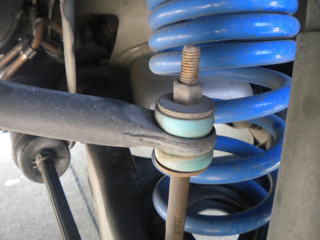
21. With the ball joint top nut secured, guide the endlink into the sway bar as the control arm is raised with the floor jack. This would also be a good time to upgrade/replace the sway bar end links. Reusing the end link hardware, place the bushing on first and then tighten the endlink top nut with the 15mm deep well socket or 15mm wrench.
22. Move the strut into place and align with the appropriate holes on the spindle. Tighten down the strut to the spindle with the 13/16” wrench or socket on the bolt and 15/16” wrench or socket on the nut. Put the brake line bracket over the strut bolts and tighten it down with the 15/16” socket.
23. Put the ABS speed sensor in place if the vehicle is equipped with ABS.
24. Place the rotor on the hub and put the caliper in place. Tighten down the (2) 15mm bolts that hold the caliper to the spindle.
25. Check all bolts before mounting the wheel.
26. Tighten down lug nuts, lower the vehicle, torque lug nuts, and remove rear wheels chocks.
27. Enjoy improved steering response.
Installation Instructions provided by AmericanMuscle customer John Collmann 8.14.12

