FREE 1 to 3-Day Delivery on Orders $149+ Details
How to Install a Whiteline Front Adjustable Anti-dive Kit on your 2005 to 2010 Mustang

Shop Parts in this Guide
Application:
-Ford Mustang 2005 - On Anti dive caster kit
Always refer to current catalogue for complete application listing.
This kit is designed to add or reduce static caster to both front wheels by 0.5 deg, while changing the nature of front anti dive.
The low compliance bush also maintains caster control during braking and cornering.
By changing the front control arm geometry, the new alloy mounts coupled with the new low compliance polyurethane bushes change front suspension attitude.
The additional positive caster coupled with the new firmer bushes supplied serve to dramatically sharpen initial turn in response,forcing more consistent alignment angles through the corner due to the reduced bush compliance.
Fitting Instructions:
Please read complete fitting instructions and check kit components prior to fitment. These instructions are to be used in conjunction with the workshop manual, and it is recommended that all work be carried out by a qualified technician.
1. Lift the front of the car with wheels at full droop and support on vehicle safety stands.
2. Remove front road wheels.
3. Remove the lower control arm rear bush bracket to crossmember bolts.
4. Remove ball joint retaining bolt and lower control arm front bush bolt.
5. Remove the lower control arm from the vehicle.
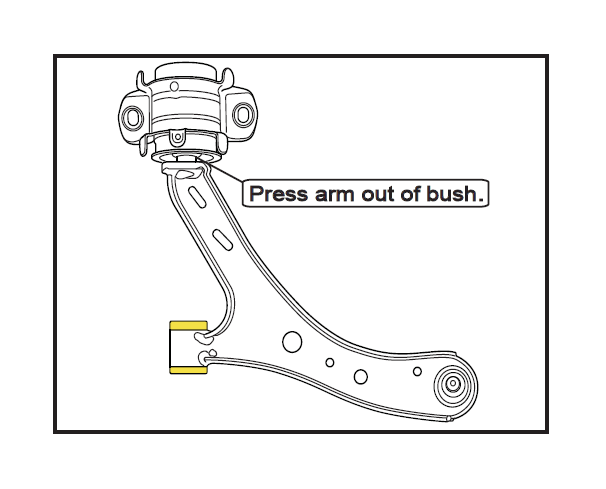
6. Using suitable press plates, press the arm out of the oe bush taking care not to damage the control arm spigot.
7. Make sure the control arm spigot is free from damage and burrs.
8. Install the control arm tubes over the spigot and gently tap down until fully seated.
9. Lubricate the inside bore and running face of the bush and install arm taking note of alloy mount orientation.
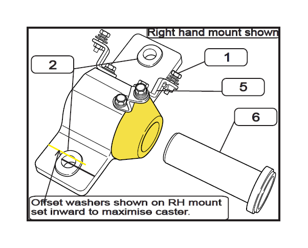
Note: When alloy brackets are installed correctly the exhaust mounting bracket holes should face inward to the centre of the vehicle .
10. Install exhaust heat shield brackets and heat shield using supplied M6 bolts.
11. Refit the control arm to the vehicle taking note of the positioning of the offset caster washers.
12. Setting both of the washers so that the hole position is offset in toward the centre of the vehicle will increase static caster angle and setting the washer offset outward will reduce static caster.
13. Re tighten ball joint and control arm bolts to manufacturers torque specifications.
14. Test drive, and re-tension all bolts.
15. Check wheel alignment, and adjust as required.
16. It is recommended to re-tension and inspect all bolts after initial settling in period of a minimum of 100kms.