FREE 1 to 3-Day Delivery on Orders $149+ Details
How to Install Wilwood AERO4 Dynamic Rear Brake Kit - Black (05-14 All) on your Ford Mustang

Shop Parts in this Guide
Important Notice - Read This First
Before any tear-down or disassembly begins, review the following information:
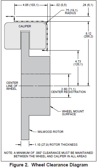
• Review the wheel clearance diagram (Figure 2, page 3) to verify that there is adequate clearance with the wheels you will be using with the installation.
• Verify the rear axle housing flange pattern, axle offset, and other critical measurements as outlined on page 3.
• Minor modifications to the axle flange may be required, see text and Figure 4 on page 4.
• Rear brake kits are not supplied with hydraulic lines or fittings and may require the purchase of additional lines or fittings to complete the installation. Wilwood offers an extensive listing of brake lines and fittings on our web site: www.wilwood.com.
• Rear brake kits are not supplied with parking brake cables hardware or adapters. Please see the note in the assembly instructions for vendor recommendations to purchase these parts.
• Due to OEM production differences and other variations from vehicle to vehicle, the fastener hardware and other components in this kit may not be suitable for a specific application or vehicle.
• It is the responsibility of the purchaser and installer of this kit to verify suitability / fitment of all components and ensure all fasteners and hardware achieve complete and proper engagement. Improper or inadequate engagement can lead to component failure.
Photographic Tip
Important and highly recommended: Take photos of brake system before disassembly and during the disassembly process. In the event, trouble-shooting photos can be life savers. Many vehicles have undocumented variations, photos will make it much simpler for Wilwood to assist you if you have a problem.
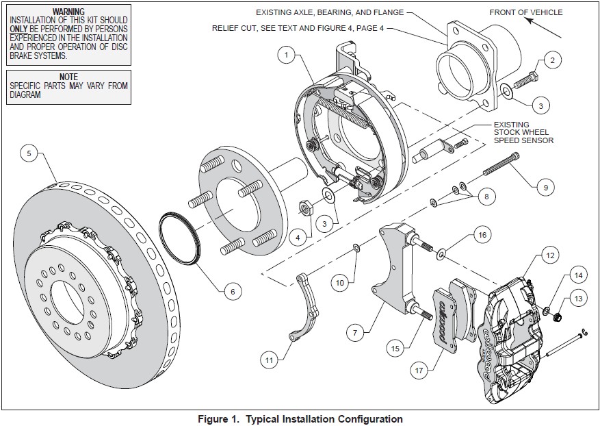
Exploded Assembly Diagram
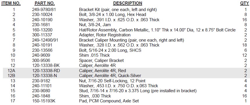
Parts List
General Information
Installation of this kit should ONLY be performed by persons experienced in the installation and proper operation of disc brake systems. Before assembling the Wilwood rear axle disc brake kit, double check the following items to ensure a troublefree installation.
•Inspect the package contents against the parts list to ensure that all components and
hardware are included.
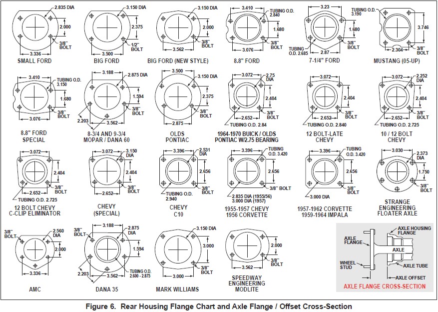
•Make sure this is the correct kit to fit the axle housing flange, not necessarily the rear end make. Many times after market manufacturers put a different make of axle housing flange on the stock rear end housing (see Figure 6). Example; Big Ford rear ends with Olds-Pontiac flanges, therefore, an Olds-Pontiac rear disc brake kit would be the correct kit to order. Also, shock clearance may be a problem. They may have to be modified and/or relocated to clear the Wilwood kit after final assembly.
•Verify your wheel clearance using Figure 2.
•Verify The Following Measurements Before Assembly.
• Axle tube outside diameter.
• Dimension from wheel side of axle flange to wheel side of axle housing flange (see Figure 6, lower right hand corner). This dimension is critical to ensure proper alignment of the rotor to the caliper, and should match offset given in the kit description.
• The Wilwood hat utilized in this kit is drilled for 1/2” diameter wheel studs. NOTE: Some OEM axles have 7/16” (0.44”) wheel axle studs. It is recommended that you upgrade to 1/2” studs. Dependent on the type of axle, this may be a simple stud change, or may require the services of a machine shop to perform.
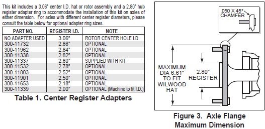
• Maximum axle flange diameter must be no larger than 6.61” w/.050” x 45° chamfer, Figure 3.
Disassembly Instructions:
•Disassemble the original equipment rear brakes: Raise the rear wheels off the ground and support the rear suspension according to the vehicle manufacturer’s instructions.
Remove the rear wheels and disassemble the brake assembly down to the bare axle. Remove wheel speed sensor from dust shield (wheel speed sensor will be reinstalled later into new backing plate assembly).
NOTE: Reference the vehicle’s dealer or shop manual for proper instructions on the removal of each rear axle shaft.
• Remove any nicks or burrs on the axle housing flange, as well as the axle flange, that may interfere with the installation of the new brake components.
• Clean and de-grease the axle and axle housing flange.
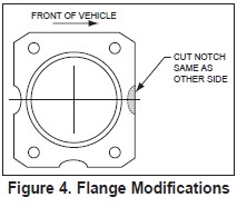
•Axle housing flange may need to be modified by grinding. A relief, the same dimension as the OEM relief at the rear of the housing must be present at the front (of vehicle) side of the housing flange, see Figure 4. This is necessary in order to reinstall the OE wheel speed sensor onto the new backing plate assembly.
Assembly Instructions
IMPORTANT:
• To ensure maximum performance from your parking brake system, the cables must be routed as straight as possible. Bends in the cable can significantly reduce efficiency and thus reduce pull force at the brake. Tight bends must be avoided with a minimum recommended bend radius of 6" to 8".
• Cables should be properly restrained to prevent "straightening" of bends when tension is applied. Restrain movement of cable by affixing the cable sheath to body or chassis by fitting cable clamps at various points over the length of cable or by using original equipment cable attachments points. The clamping method chosen will require that cable sheath be held tightly without movement, crushing or causing interference to the internal cable.
• Cables must be initially pre-stretched by multiple applications of the brake handle, then re-adjusted to correct tension.
Assembly Instructions (numbers in parenthesis refer to the parts list, and Figure 1 on the preceding pages): CAUTION: All mounting bolts must fully engage threaded holes.
•Orient the bracket assembly (1), as shown in Figure 1, and mount to the axle housing flange using bolts (2), washers (3) and nuts (4), Figure 1. Ensure that the bracket assembly backing plate fits flush against the axle housing flange. Apply red Loctite® 271 to the bolt threads and torque to 30 ft-lbs.
•Install the axle into the rear end housing.
• The hat/rotor assembly (5) has been pre-assembled at the factory using red Loctite® 271 on the mounting bolts and torqued to specification For an added measure of security, the bolts may be safety wired using standard 0.032 inch diameter stainless steel safety wire as shown in Figure 5. Please refer to Wilwood’s data sheet DS-386 (available at www.wilwood.com/Pdf/DataSheets/ds386.pdf) for complete safety wire installation instructions.
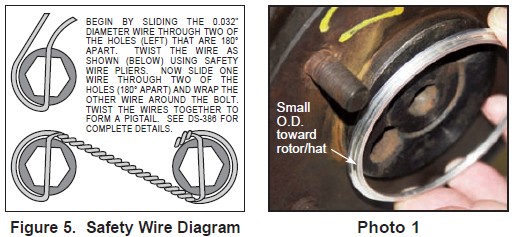
•Slide the rotor registration adapter (6) onto the axle flange with the smaller O.D. facing toward the rotor/hat, Photo 1.
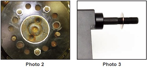
•Align the correct hole pattern in the rotor/hat with the stud pattern on the axle flange and slide into place, Figure 1 and Photo 2. NOTE: The rotor/hat must fit flush against the axle flange or excessive rotor run out may result. Install three lug nuts (finger tight) to keep the rotor/hat assembly in place while continuing with the installation. NOTE: Some OEM and after market axles come with stud sizes larger than 0.50” diameter. Verify stud size and have a qualified machine shop drill the bolt circle of the hat/rotor to the correct stud size, if necessary.
•NOTE: Please reference the caution statement at the beginning of the assembly instructions. The caliper mounting bracket (7) should be installed first with clean, dry threads on the mounting bolts. Install the caliper bracket to the bracket kit assembly (1) using bolts (9), three washers (8), and spacer (11), as shown in Figure 1. Initially place one .015” thick shim (10) on each bolt between spacer and the caliper bracket. Temporarily tighten the mounting bolts. NOTE: The bracket must tighten squarely against the back side of the bracket kit assembly. Inspect for interference from casting irregularities, machining ridges, burrs, etc. Later, after the caliper alignment has been checked, the mount bolts will be secured using red Loctite® 271.
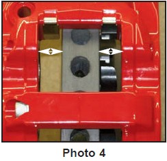
•NOTE: This kit contains distinct right and left hand calipers that must be mounted in a specific direction, as described below. Lubricate the caliper mounting studs (15) with lightweight oil. Initially place one .030” thick shim (16) on each stud between the caliper and the bracket, as shown in Figure 1 and Photo 3. Mount the caliper (12) onto the bracket (7) using lock nuts (13) and washers (14), Figure 1. Temporarily tighten the lock nuts. Ensure that the caliper is mounted so the largest pistons are at the rotor exit end of the caliper, in relation to the direction of the rotor. View the rotor through the top opening of the caliper. The rotor should be centered in the caliper, Photo 4. If not, adjust by adding or subtracting shims (10) between the bracket and the spacer. Always use the same amount of shims on each of the three mounting bolts. NOTE: The ends of the mounting bolts must fully engage, but not exceed, the inside face of the clinch nuts in the backing plate. If needed, add or substract spare shims (10) and/or washers (8) under the bracket bolt heads to achieve proper clinch nut engagement. Once the caliper alignment and clinch nut engagement are correct, remove the bracket mounting bolts one at a time, apply red Loctite® 271 to the threads, and torque to 220 in-lbs.
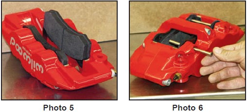
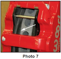
• Remove the two pad retaining pins from the caliper (12) by carefully popping out the pin retaining clips and sliding out the pins. Insert the brake pads (17) into the caliper from the bottom, Figure 1 and Photo 5. With the friction material facing the rotor, secure the brake pads in place with the pad retaining pins and clips, Photo 6. Reinstall the caliper onto the caliper mounting bracket and temporarily tighten the lock nuts. Check that the top of the brake pad is flush with the outside diameter of the rotor, Photo 7. If not, adjust by adding or subtracting shims (11) between the caliper and the bracket. After the caliper pad height is set, torque the caliper lock nuts (13) to 47 ft-lb.
•Temporarily install wheel and torque lug nuts to manufacturer’s specification. Ensure that the wheel rotates freely without any interference.
•NOTE: Clevis and cable kits which attach to the parking brake assembly are not included in the Wilwood parking brake kit. Wilwood offers a parking brake cable kit, P/N 330-11221 for years 2005- 2010, or P/N 330-12335 for years 2011-present for this application which can be ordered separately from your local Wilwood dealer or by calling Wilwood customer service at (805) 388-1188.
•Before final installation of the wheel, install three lug nuts, remove the rubber grommet in the bracket kit assembly (1) and adjust the parking brake shoes outward (using a drum shoe adjustment tool available at your local auto parts store) while spinning the rotor/hat (5) until a slight drag is felt against the hat/drum. Replace the rubber grommet when finished.
•NOTE: OEM rubber brake hoses generally cannot be adapted to Wilwood calipers. The caliper inlet fitting is a 1/8-27 NPT. The preferred method is to use steel adapter fittings at the caliper, either straight, 45 or 90 degree and enough steel braided line to allow for full suspension travel. Carefully route hoses to prevent contact with moving suspension, brake or wheel components. NOTE: Wilwood hose kits are designed for use in many different vehicle applications and it is the installer's responsibility to properly route and ensure adequate clearance and retention for brake hose components. Wilwood offers a brake flex line hose kit specifically for this kit, order P/N 220-9248. Hose kits include hoses, fitting, etc., all in one package for this application.
•NOTE: Specified brake hose kits may not work with all Years, Makes and Models of vehicle that this brake kit is applicable to, due to possible OEM manufacturing changes during a production vehicle's life. It is the installer's responsibility to ensure that all fittings and hoses are the correct size and length, to ensure proper sealing and that they will not be subject to crimping, strain and abrasion from vibration or interference with suspension components, brake rotor or wheel.
•In absence of specific instructions for brake line routing, the installer must use his best professional judgment on correct routing and retention of lines to ensure safe operation. Test vehicle brake system per the 'minimum test' procedure stated within this document before driving. After road testing, inspect for leaks and interference. Initially after install and testing, perform frequent checks of the vehicle brake system and lines before driving, to confirm that there is no undue wear or interference not apparent from the initial test. Afterwards, perform periodic inspections for function, leaks and wear in a interval relative to the usage of vehicle.
• Bleed the brake system, referring to the additional information and recommendations on page 8 for proper bleeding instructions. Check system for leaks after bleeding.
• Install the wheel and torque to manufacturer’s specifications.
Balancing the Brake Bias on 4 Wheel Disc Vehicles
•OE Style or Single Mount Race Pedal with Tandem Outlet Master Cylinder: Front to rear caliper piston sizes, rotor diameters, and pad compounds must be initially configured to provide the correct range of vehicle bias when using a single bore / tandem outlet master cylinder. If excessive rear brake bias is experienced, an in-line adjustable proportioning valve can be used to decrease the rear line pressure to help bring the vehicle into balance. If excessive front brake bias is experienced, first consideration should be given to increasing the rear brake bias to bring the vehicle into overall balance.
•Race Pedal with Dual Master Cylinders and Balance Bar: Master cylinders must be sized to match the calipers and allow the pedal balance bar to operate near the center of its travel. If it is not possible to fine tune the bias within the adjustable range of the balance bar, then consideration must be given to changing a master cylinder bore size or some other aspect of the brake system to bring the car into balance. Larger bore master cylinders will generate less pressure while decreasing pedal travel. Smaller bores master cylinders will generate higher line pressures with an increase in pedal travel.
Additional Information and Recommendations
•Fill and bleed the new system with Wilwood Hi-Temp° 570 grade fluid or higher. For severe braking or sustained high heat operation, use Wilwood EXP 600 Plus Racing Brake Fluid. Used fluid must be completely flushed from the system to prevent contamination. NOTE: Silicone DOT 5 brake fluid is NOT recommended for racing or performance driving.
•To properly bleed the brake system, begin with the caliper farthest from the master cylinder. Bleed the outboard bleed screw first, then the inboard. Repeat the procedure until all calipers in the system are bled, ending with the caliper closest to the master cylinder. NOTE: When using a new master cylinder, it is important to bench bleed the master cylinder first.
•If the master cylinder is mounted lower than the disc brake calipers, some fluid flowback to the master cylinder reservoir may occur, creating a vacuum effect that retracts the caliper pistons into the housing. This will cause the pedal to go to the floor on the first stroke until it has “pumped up” and moved all the pistons out against the pad again. A Wilwood in-line two pound residual pressure valve, installed near the master cylinder will stop the fluid flowback and keep the pedal firm and responsive.
•Test the brake pedal. It should be firm, not spongy and stop at least 1 inch from the floor under heavy load. If the brake pedal is spongy, bleed the system again.
If the brake pedal is initially firm, but then sinks to the floor, check the system for fluid leaks. Correct the leaks (if applicable) and then bleed the system again.
If the brake pedal goes to the floor and continued bleeding of the system does not correct the problem, a master cylinder with increased capacity (larger bore diameter) will be required. Wilwood offers various lightweight master cylinders with large fluid displacement capacities.
•NOTE: With the installation of after market disc brakes, the wheel track may change depending on the application. Check your wheel offset before final assembly.
•On some models of disc brake spindles there are “ears” where the OEM calipers were mounted and these “ears” interfere with the assembly of the Wilwood disc brake kit. If it becomes necessary to remove these “ears”, remove as little as possible being careful not to cut away any of the mounting holes that may be required to bolt on the caliper mounting bracket.
•If after following the instructions, you still have difficulty in assembling or bleeding your Wilwood disc brakes, consult your local chassis builder, or retailer where the kit was purchased for further assistance.
Brake Testing
WARNING • DO NOT DRIVE ON UNTESTED BRAKES BRAKES MUST BE TESTED AFTER INSTALLATION OR MAINTENANCE MINIMUM TEST PROCEDURE
• Make sure pedal is firm: Hold firm pressure on pedal for several minutes, it should remain in position without sinking. If pedal sinks toward floor, check system for fluid leaks. DO NOT drive vehicle if pedal does not stay firm or can be pushed to the floor with normal pressure.
• At very low speed (2-5 mph) apply brakes hard several times while turning steering from full left to full right, repeat several times. Remove the wheels and check that components are not touching, rubbing, or leaking.
• Carefully examine all brake components, brake lines, and fittings for leaks and interference.
• Make sure there is no interference with wheels or suspension components.
• Drive vehicle at low speed (15-20 mph) making moderate and hard stops. Brakes should feel normal and positive. Again check for leaks and interference.
• Always test vehicle in a safe place where there is no danger to (or from) other people or vehicles. • Always wear seat belts and make use of all safety equipment.
Pad and Rotor Bedding
BEDDING STEPS FOR NEW PADS AND ROTORS – ALL COMPOUNDS
Once the brake system has been tested and determined safe to operate the vehicle, follow these steps for the bedding of all new pad materials and rotors. These procedures should only be performed on a race track, or other safe location where you can safely and legally obtains speeds up to 65 MPH, while also being able to rapidly decelerate.
• Begin with a series of light decelerations to gradually build some heat in the brakes. Use an on-and-off the pedal technique by applying the brakes for 3-5 seconds, and then allow them to fully release for a period roughly twice as long as the deceleration cycle. If you use a 5 count during the deceleration interval, use a 10 count during the release to allow the heat to sink into the pads and rotors.
• After several cycles of light stops to begin warming the brakes, proceed with a series of medium to firm deceleration stops to continue raising the temperature level in the brakes.
• Finish the bedding cycle with a series of 8-10 hard decelerations from 55-65 MPH down to 25 MPH while allowing a proportionate release and heat-sinking interval between each stop. The pads should now be providing positive and consistent response.
• If any amount of brake fade is observed during the bed-in cycle, immediately begin the cool down cycle.
• Drive at a moderate cruising speed, with the least amount of brake contact possible, until most of the heat has dissipated from the brakes. Avoid sitting stopped with the brake pedal depressed to hold the car in place during this time. Park the vehicle and allow the brakes to cool to ambient air temperature.
COMPETITION VEHICLES
• If your race car is equipped with brake cooling ducts, blocking them will allow the pads and rotors to warm up quicker and speed up the bedding process.
• Temperature indicating paint on the rotor and pad edges can provide valuable data regarding observed temperatures during the bedding process and subsequent on-track sessions. This information can be highly beneficial when evaluating pad compounds and cooling efficiencies.
POST-BEDDING INSPECTION – ALL VEHICLES
• After the bedding cycle, the rotors should exhibit a uniformly burnished finish across the entire contact face. Any surface irregularities that appear as smearing or splotching on the rotor faces can be an indication that the brakes were brought up to temperature too quickly during the bedding cycle. If the smear doesn’t blend away after the next run-in cycle, or if chatter under braking results, sanding or resurfacing the rotors will be required to restore a uniform surface for pad contact.
PRE-RACE WARM UP
• Always make every effort to get heat into the brakes prior to each event. Use an on-and-off the pedal practice to warm the brakes during the trip to the staging zone, during parade laps before the flag drops, and every other opportunity in an effort to build heat in the pads and rotors. This will help to ensure best consistency, performance, and durability from your brakes.
DYNO BEDDED COMPETITION PADS AND ROTORS
• Getting track time for a proper pad and rotor bedding session can be difficult. Wilwood offers factory dyno-bedded pads and rotors on many of our popular competition pads and Spec 37 GT series rotors. Dyno-bedded parts are ready to race on their first warm up cycle. This can save valuable time and effort when on-track time is either too valuable or not available at all, Dyno-bedding assures that your pads and rotors have been properly run-in and are ready to go. Contact your dealer or the factory for more information on Wilwood Dyno-Bedding services.
NOTE: NEVER allow the contact surfaces of the pads or rotors to be contaminated with brake fluid. Always use a catch bottle with a hose to prevent fluid spill during all brake bleeding procedures.
Parking Brake
WARNING • PARKING BRAKE
• Parking brake must be properly adjusted before use and must be manually readjusted for wear if parking brake handle or foot lever travel becomes excessive.
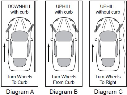
• The holding ability of the brake should be tested by stopping on a sloping surface and applying the parking brake while holding car with the hydraulic foot brake. This should be accomplished both facing up and down hill.
• Do not rely exclusively on the parking brake to hold the car; Curb wheels as recommended by the applicable diagram and put gear selector in park, or shift into first gear or reverse with a manual transmission.
• Diagram A - When parking facing downhill, turn front wheels towards the curb or right shoulder. This will keep from rolling into traffic if the brakes become disengaged.
• Diagram B - Turn the steering wheel to the left so the wheels are turned towards the road if you are facing uphill with a curb. The tires will catch the curb if the car rolls backward.
• Diagram C - When facing uphill without a curb, turn the wheels sharply to the right. If the vehicle rolls, it will go off the road rather than into traffic.
• When parking on a hill, always set the parking brake and move the gear selector into park, or shift into first or reverse gear if your vehicle has a manual transmission.