FREE 1 to 3-Day Delivery on Orders $149+ Details
How to Install Canton Aluminum Expansion Tank for Roush Superchargers on your Mustang

Shop Parts in this Guide
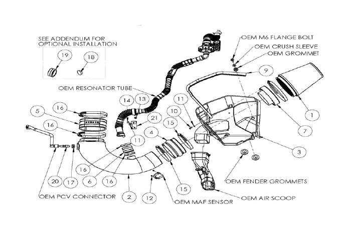
Component Identification
1. Airaid Premium Filter 1
2. Airaid Intake Tube 1
3. Cool Air Box 1
4. Urethane Hump Hose 1
5. Urethane Oval Coupler 1
6. Urethane 1 3/4" Coupler 1
7. Filter Adapter 1
8. 3/8" x 12" Hose 1
9. Weather Strip 25" 1
10. ¼-20 x 1/2” Button Head Cap Screw 3
11. 1/4” Flat Washer 4
12. 8-32 x 3/8” Button Head Cap Screw 2
13. 1/4-20 X 0.875 Hex Bolt 1
14. M6x1.0x12 Hex Bolt 1
15. #72 Hose Clamp 4
16. 60mm Hose Clamp 2
17. GROMMET 1
18. Firewall Plug 1
19. Urethane Cap* 1
20. PCV Connector Fitting 1
21. Resonator Tube Bracket 1
22. #20 Torx Driver 1
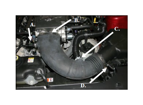
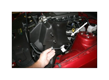
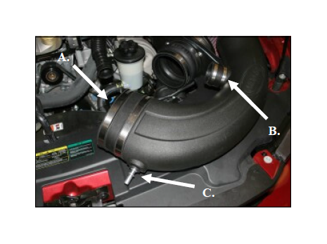
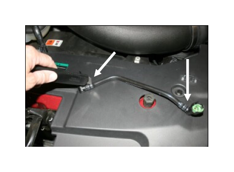
1. Disconnect the negative battery cable. A.) Push the green plastic tabs on each end, and remove the breather hose from vehicle. (Save for later use). B.) Loosen the hose clamp that secur es the intake tube to the throttlebody. C.) Squeeze the clamp and disconnect the resonator from the air intake tube. D.) Slide the red tab, and disconnect the wiring harness from the Mass Air Flow sensor (MAF).
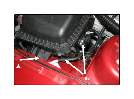
2.A.) Using a 10mm socket, remove and save the bolt that secures the airbox to the fender.
B.) Using a flat blade screwdr iver , carefully, push, or pry the 5 wiring loom anchors from the factory airbox.
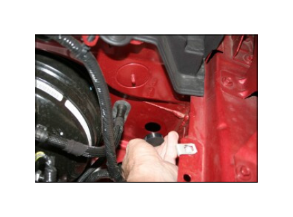
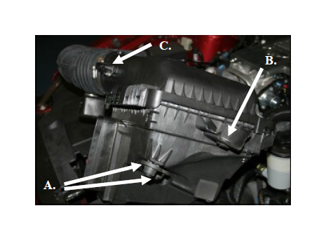
3. Grab the airbox and tube and roll it forward while lifting up to dislodge it from the intake scoop. Remove the assembly from the vehicle. A.) Remove the two factory grommets and then replace them back into the two holes in the inner fender. B.) Remove the steel sleeve and grommet and save for reinstallation later. C.) Using the provided #20 Torx bit, remove the two screws and the MAF sensor from the tube.
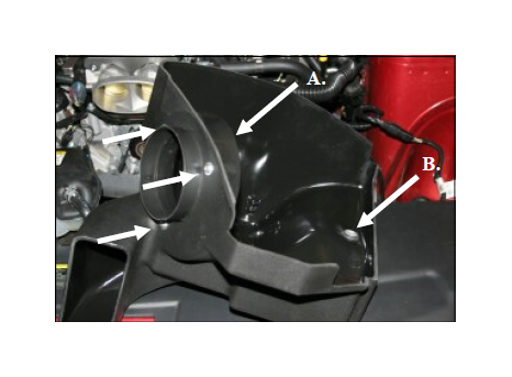
4. A.) Install the filter adapter (#7) using three 1/4-20 button head bolts (#11), and flat washers (#10) into the Airaid Cool Air Box (CAB) (#3) as shown. B.) Reinstall the small grommet and sleeve (removed in step #3) into the hole in the CAD.
5. Turn the CAB so that the bottom faces the left fender as shown. Now reinstall the wiring loom anchors into their respective holes starting at the back of the CAB with the two hole anchor and work your way underneath and towards the front. The last anchor nearest the MAF sensor is not anchored.
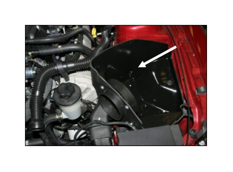
6. Install the CAB into the vehicle making sure that the scoop provision in the CAB aligns with the factory scoop, and the two locating pins on the bottom align with the factory grommets. Next reinstall the factory bolt that was removed in step #2 thru the steel sleeve and grommet and into the inner fender. Make sure that the wiring harness is not pinched under the CAB.
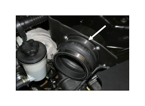
7. Install the provided hump hose (#4) onto the filter adapter using two #72 hose clamps (#15) as shown. Leave the two hose clamps loose for now.
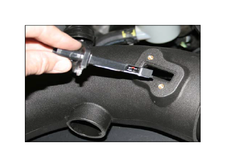
8. Install the MAF sensor into the intake tube using two provided 8-32x3/8” screws (#12). Do Not Use The Factory Screws!
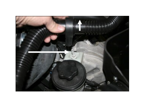
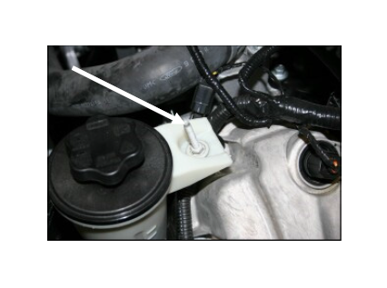
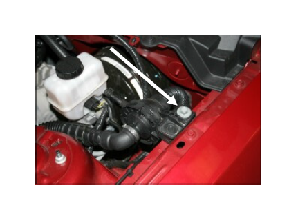
9. Lift up on the intake resonator tube to disengage it from the stud securing the power steering reservoir. Using a deep 10mm socket, remove the stud and save it for a possible optional install. See step #18.
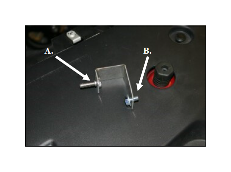
10.A.) Thread the 1/4-20 hex bolt (#13) into the resonator bracket (#21) and tighten as shown.
B.) Slide the 6mmx12mm (#15) hex bolt thru one flat washer (#11) and into the hole in the resonator bracket.
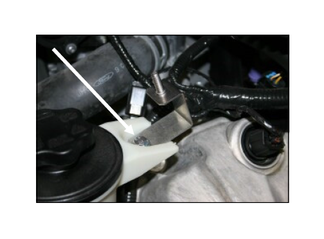
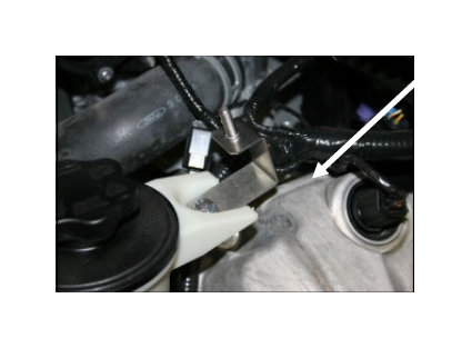
11. Install the bracket assembly from step #10 as shown. This bracket and 6mm bolt will secure the power steering reservoir and replaces the stud removed in step #9.
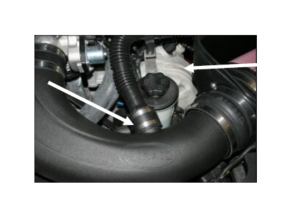
12.A.) Install the oval coupler onto the intake tube using two #72 hose clamps (#15). Leave the clamps loose for now. B.) Install the 1 3/4” coupler (#6) onto the intake tube using two #28 hose clamps (#16) as shown. Tighten only the clamp against the tube for now. C.) Install the provided grommet (#17) into the intake tube and then install the aluminum fitting (#20) into the grommet as shown.
13. Install the air intake tube into the hump hose first, and then onto the throttlebody. Adjust for fit and then tighten all four hose clamps. Next, reinstall the factory resonator tube into the 1 3/4” coupler and tighten the hose clamp. Now “reseat” the resonator tube onto the bracket.
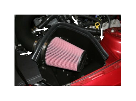
14. Install the Airaid Premium Filter (#1) onto the filter adapter and tighten the hose clamp. Next, install the weatherstrip (#9) onto the top of the CAD as shown starting near the radiator and working your way towards the left fender.
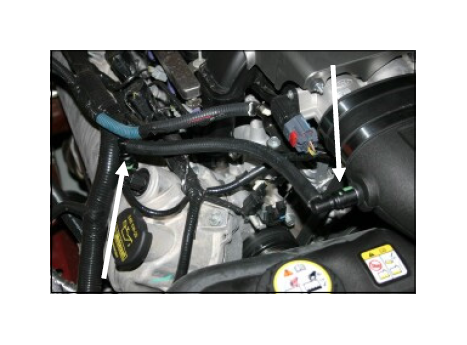
15. VERY CAREFULLY! Without cutting thr u the connectors, cut the factory breather tube on each end just enough to remove the factory connectors.
16. Install the two factory connectors from step #15 into each end of the supplied 3/8”x12” breather hose (#9). Now reattach one connector to the valve cover, and the other end to the aluminum fitting on the intake tube.
17. Double check your work! Make sure there is no foreign material in the intake path. Make sure all clamps, hoses, bolts, and screws are tight. Double check the hood clearance! Reconnect the negative battery cable!
18. Optional Installation Notice! Airaid has made provisions to eliminate the factory air intake resonator if you so desire. The removal of the resonator has no effect negative effect on the performance of this kit. Please see the addendum instruction sheet included with these instructions for further information.
As an option, Airaid has made a provision for those who would like to remove the air intake sound resonator on your 4.6L engine. The following instructions will allow you to remove the resonator while still retaining maximum performance. You can perform the steps below after you install the complete kit, or you can substitute these steps while you do the install.
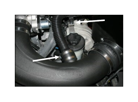
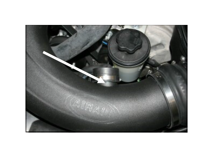
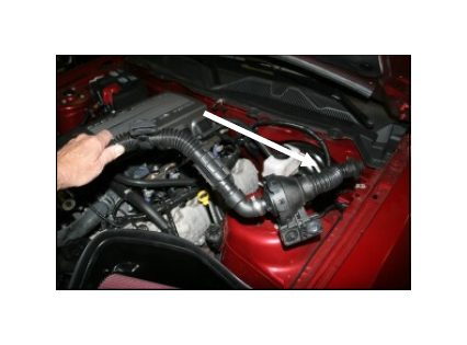
1. Loosen the clamps on the resonator tube coupler and disconnect it from the intake tube. Pull up on the resonator tube to release it from the resonator
2. Using one of the clamps from the resonator coupler, install the urethane cap onto the intake tube and tighten the clamp.
3. Using a 10mm socket, remove the resonator bracket from the power steering reservoir.
4. Replace the resonator bracket and 6mm bolt with the factory stud removed in step #9.
5. Remove the bolt that secures the resonator tube and diaphragm to the left inner fender.
6. Grab the resonator tube between the diaphragm and the firewall and pull up and out to disconnect it from the firewall. Remove the complete resonator assembly from the vehicle.
7. Install the optional firewall plug (#19 on the main page) into the hole in the firewall.