 FREE 1 to 3-Day Delivery on Orders $149+ Details
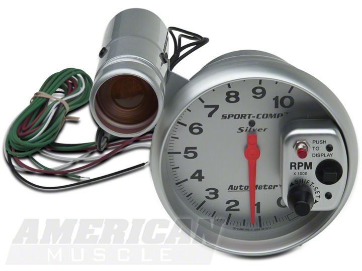
How to Install an Auto Meter Sport Comp 5in Tachometer w/ Shift Light on Your 1979-2012 Mustang
Shop Parts in this Guide
Installation
Any Auto Meter Shift-Lite™, or Quick-Lite™ Shift-Lite can be used with tachs equipped with a black, Shift-Lite connector.
NOTE 1: This tachometer has an air core meter. With power off, it is normal for the pointer to leave zero. When 12V power is applied, the pointer will move to the correct position.
NOTE 2: Tachometers with two or three buttons use an advanced microcontroller circuit to measure engine RPM for increased accuracy and zero pointer flutter at low RPM. When used on 0.5, 1, or 1.5 pulse per rev ignitions, a brief pause in pointer movement may be observed as RPM is rapidly decreased.
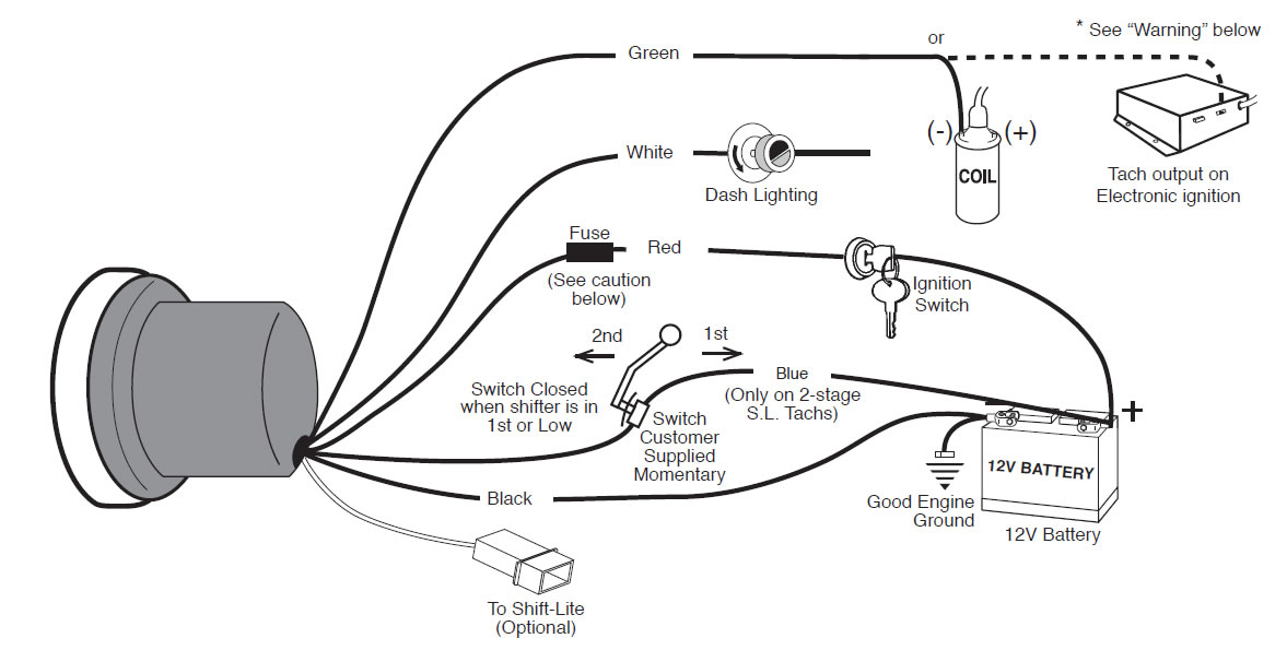
- WIRING
WARNING
Warranty will be void if connected to coil when using an aftermarket ignition box such as, but not limited to products from the following manufacturers: MSD, Crane, Jacobs, Mallory, Holley, Etc.. Prior to installation of your tachometer, check with the ignition box manufacturer for recommended tachometer signal location.
Caution !!!
As a safety precaution the RED wire of this product should be fused before connecting it to the positive ( ) side of switched power source. We recommend using a 4 Amp, 3AG fast-acting type cartridge fuse (Littlefuse® #312 004 or an equivalent) inline with the RED wire of our product for tachs that use a Shift-Lite. For tachs without a Shift-Lite we recommend using a 1Amp 3 AG fast-acting type cartridge fuse (Littlefuse® #312 001 or an equivalent).
WARNING
Check with engine builder for maximum recommended safe shift point before setting shift point on tachometer. Failure to do this could lead to over-revving of engine, causing serious damage to engine and car.
IMPORTANT NOTE
This tach has an air core meter movement. The tach pointer may not always rest at zero. This is normal. When 12v power is supplied, pointer will position to the correct RPM.
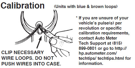
8 CYL. (4 Pulse) — NO adjustment is necessary.
6 CYL. (3 Pulse) — Clip BROWN wire loop only. Insulate with electrical tape.
4 CYL. (2 Pulse) — Clip BLUE wire loop only. Insulate with electrical tape.
4 CYL. (1 Pulse) — Clip BROWN and BLUE wire loops. Insulate with electrical tape.
2. CALIBRATION (MODELS WITH NO CALIBRATION LOOPS)
The tachometer is configured at the factory for 4 PPR. To change the PPR on tachs with three buttons, follow the steps below:
1. With no power applied to the tach, press and hold the SET button.
2. Apply power to the tach by turning the ignition key to the “Accessory” or “On” position. Do not start the engine! The pointer will move to a position on the dial which indicates the default configuration of 4 PPR. Release the SET button.
3. Press and release the (erase) button to increase the PPR setting. Press and release the (recall) button to decrease the PPR setting.
See the tables below to find the pointer reading that corresponds to the desired PPR for your tachometer type.
4. When the pointer indicates the desired PPR, press and release the SET button to permanently store the settings and exit Configuration mode.
To change the PPR on tachs with two buttons, follow the steps below:
1. With no power applied to the tach, press and hold the yellow RECALL button.
2. Apply power to the tach by turning the ignition key to the “Accessory” or “On” position. Do not start the engine! Release the RECALL button.
The pointer will move to a position on the dial which indicates the default configuration of 4 PPR.
3. Press and release the red ERASE button to change the PPR setting. This will cause the pointer to indicate 5 PPR, then 6 PPR, then down to 0.5 PPR, then 1, 1.5, 2, 2.5, 3, and back to 4 PPR. See the table below to find the pointer reading that corresponds to the desired PPR.
4. When the pointer indicates the desired PPR, press and release the yellow RECALL button to permanently store the settings and exit Configuration mode
FOR MODELS 6858, 6857, 6856, 3906 AND 6851:
| ENGINE | Most 2 cyl. | Most 4 cyl. | Most 6 cyl. | Most 8 cyl. | |||||
| PPR | 0.5 | 1 | 1.5 | 2 | 2.5 | 3 | 4 | 5 | 6 |
| DIAL RPM | 500 | 1000 | 1500 | 2000 | 2500 | 3000 | 4000 | 5000 | 6000 |
FOR MODELS 6809, 6811, 6854, 4499, 6852 and 5795
| ENGINE | Most 2 cyl. | Most 4 cyl. | Most 6 cyl. | Most 8 cyl. | |||||
| PPR | 0.5 | 1 | 1.5 | 2 | 2.5 | 3 | 4 | 5 | 6 |
| DIAL RPM | 5000 | 5500 | 6000 | 6500 | 7000 | 7500 | 8000 | 8500 | 9000 |
FOR MODEL 6855:
| ENGINE | Most 2 cyl. | Most 4 cyl. | Most 6 cyl. | Most 8 cyl. | |||||
| PPR | 0.5 | 1 | 1.5 | 2 | 2.5 | 3 | 4 | 5 | 6 |
| DIAL RPM | 7000 | 7500 | 8000 | 8500 | 9000 | 9500 | 10000 | 10500 | 11000 |
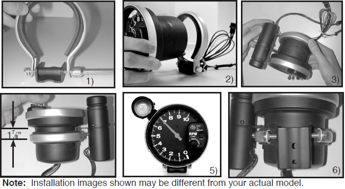
Mounting
1. Loosen both bolts holding the shock strap to the mounting foot. Back both bolts out until each is only one or two turns into the spacer.
2. Pass tach wires through shock strap assembly and slide tach casing into shock strap assembly.
3. For external Shift-Lite models, position Shift-Lite mounting bracket under shock strap as shown in image. Adjust Shift-Lite (if applicable), tach, and mounting base to desired positions (see figure 4 for recommended shock strap position), and tighten bolts holding mounting foot to shock strap to secure the assembly.
4. Make sure rubber section of shock strap seats properly to ensure proper fitment. Check to make sure shock strap is approximately 17⁄8" (1.875”) between center line of strap and step of tachometer casing for best mounting. For external Shift-Lite models, plug shift light into tachometer connector. Plug is directional, do not force fit!
5. Recommended placement of external Shift-Lite (if applicable) is at 10 o’clock position. It is possible to place Shift-Lite in other positions in accordance with driver preference and vehicle mounting requirements.
6. The special design of the tachometer base allows for a variety of mounting possibilities. Attach the base using screws provided or use a pop rivet tool.
TACHOMETER
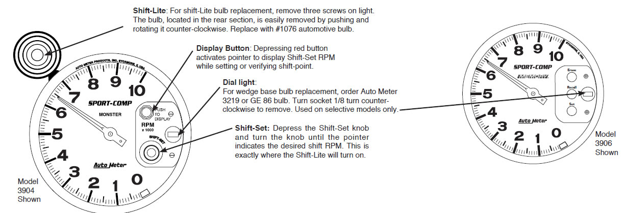
1. Push and hold red button. Pointer will display the tachometer’s shift-point and the Shift Lite will activate.
2. To set your desired shift-point, continue depressing the red button, then push and turn the Shift-Set knob until the pointer reaches the desired RPM.
3. To double check, push red set button-- pointer will indicate your shift-point.
4. During normal tachometer operation, the Shift-lite will activate at the exact same RPM that the pointer indicates when red set button is depressed.
1. Two-Stage Shift-Lite Set Mode (For tachs with two shift-lite set points)
1. To enter this mode, apply power to the tach with the engine off (no RPM signal to the tach).
2. Press and release the SET button. The pointer moves from 0 RPM to 1K RPM. This is the indicator for the Low Set shift point.
3. Press and release the SET button to review and/or set the Low Set shift point.
4. Using the “erase” and “recall” buttons, move the pointer to the desired RPM for the Low Set shift point.
5. Once the pointer is positioned at the desired RPM, press & release the SET button to store the setting.
6. Press and release the “ ” button. The pointer moves from 1K RPM to 2K RPM. This is the indicator for High Set shift point.
7. Press and release the SET button to review and/or set the High Set shift point.
8. Using the “erase” and “recall” buttons, move the pointer to the desired RPM for the High Set shift point.
9. Once the pointer is positioned at the desired RPM, press & release the SET button to store the setting.
NOTE: If the Low Set shift point has been changed, the High Set shift point will also be changed to the same value.
2. Two-Stage Shift-Lite Application (For tachs with two shift-lite set points)
1. To accomplish changing the shift setting, a Blue lead is brought out of the tachometer to a switch that the driver may manually push. (See diagram in the wiring section.)
2. When the switch is closed (pushed), the Blue lead will be connected to 12V Power and the Low Set mode will be in effect. When the switch is open (released), the High Set mode will be in effect.
3. Some racers mount the switch on the transmission or shifter such that when in first gear the switch is closed, thus placing them in Low Shift set mode. When shifted out of 1st (Low) , the switch returns to open and places the shift point in the High Set mode.
NOTE: If you prefer to use only one shift point, do not connect the Blue wire as shown in the diagram in the Wiring section and only set the High Shift Point.
3. Memory Function (For Models with Memory)
1. Press “ERASE” button before each race. This clears the memory from your previous run. You are now ready to record.
2. Press “RECALL” button to display highest RPM reached. This can be done during or after a race.
3. Memory is retained even when power to the tachometer is off.
Installation Tips
1. Mount tach base firmly to reduce vibration, wear and tear.
2. Avoid contact of the tach with windshield or other objects to maintain rubber shock absorbing feature.
3. A 12 V power source MUST be used to power this tachometer. A 12V motorcycle battery is a good alternative for cars without batteries. A battery with minimum 5 amp hour rating is recommended.
4. Avoid connecting tach power and ignition power leads together. Use separate battery leads for ignition and tach to avoid excess voltage drop.
5. Wherever possible, solder wire connections and avoid crimp-type connectors. This will minimize loose connections that could cause problems later.
6. Make sure you have a good ground to engine and battery negative terminal.
7. Wire installations should be neat and tied down to prevent tugging and fraying of wires at connections.
Trouble Shooting
If your tach does not function properly after installation check the following:
1. Are all electrical connections correct and tight?
2. If neither tach nor dial light work, check ground and 12V power connections.
3. Disregard tach readings that occur before engine is started.
4. If problems persist try tach on another vehicle with the same ignition.
5. For changes in ignition type, contact a service representative from Auto Meter.
6. Ignition manufacturers recommend that the ignition and coil be matched according to criteria which they establish (often that the ignition and coil be products of the same company).
If they are mismatched, minor malfunctions may occur, showing as erratic readings on the tach. Mismatching coil and ignition types is often the cause of incorrect tach performance.
