FREE 1 to 3-Day Delivery on Orders $149+ Details
How to Install AWE SwitchPath Cat-Back Exhaust - Fastback on your Mustang
Installation Time
2 hours
Tools Required
- 7/16” or 11mm Socket
- 13mm Socket
- 15mm Socket
- Wire Strippers

Shop Parts in this Guide
Hardware Kit:
4 3.0” (76.2mm) Accu-Seal clamps
2 3.0” (76.2mm) T-Bolt clamp
1 SwitchPathTM remote installation kit
STEP 1:
Installation of the AWE performance exhaust system is the reverse of the OEM exhaust removal.
Always refer to the manufacturer service manual for precise torque specifications on all OEM fasteners.
Before removing the factory exhaust, soak the fasteners that hold the exhaust in place with a penetrating oil.
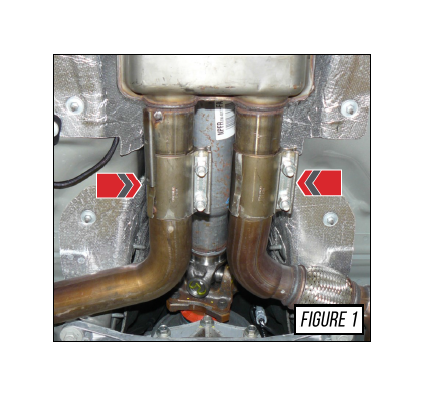
Loosen the two (2) factory sleeve clamps located just forward from the mid muffler with a 15mm socket, as shown by the arrows in Figure 1.
Note the sleeve orientation so the clamps can be reinstalled the same way.
STEP 2:
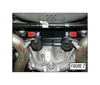
Remove the 13mm bolts that secure the factory exhaust hangers located behind the rear differential, shown by the arrows in Figure 2.
Ensure the exhaust hanger bracket drops into the catch slots on the cross-member.
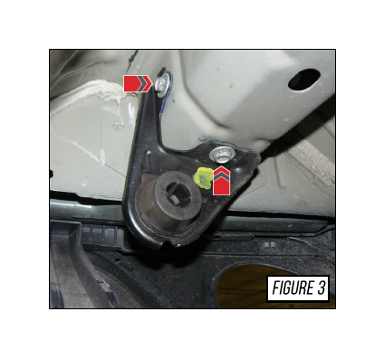
STEP 3:
Remove the 13mm bolts securing the hanger brackets located at the rear of the vehicle, shown by the arrows in Figure 3.
Ensure the exhaust hanger bracket drops into the catch slots on the frame rail.
With all the bolts from the hanger brackets removed, the factory exhaust can be removed from the car.
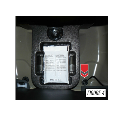
STEP 4:
Disconnect the battery before performing any electrical work.
The arrow in Figure 4 shows the passenger side drainage stop located in the trunk. Make a small incision to pass the longest leg of the SwitchPathTM control harness through to the outside of the vehicle, leaving the control box inside of the trunk.
Splice the red wire to an ignition-switched power wire found in the factory trunk wire harness.
Connect the remaining black wire to any reliable ground source on the car.
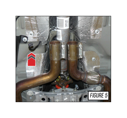
STEP 5:
From the underside of the vehicle, route the longest leg of the harness between the heat shield and floor pans, up to the location shown by the arrow in Figure 5.
Keep the harness tucked/routed away from any potentially hot exhaust or sharp components.
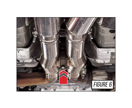
STEP 6:
Install the AWE H-Pipe section (part XF), reusing the original sleeve clamps that were loosened in Step 1. Match the original orientation.
Connect the SwitchPathTM control harness to the valve on the H-pipe section, shown by the arrow in Figure 6.
Pre-install two 3.0” Accu-Seal clamps onto the outlet section of the H-Pipe.
Reconnect the battery, then turn the ignition key to the “on” position without starting the car. To ensure proper operation of the valve, push the “on” & “off” buttons on the included SwitchPathTM remotes to ensure proper operation.
STEP 7:
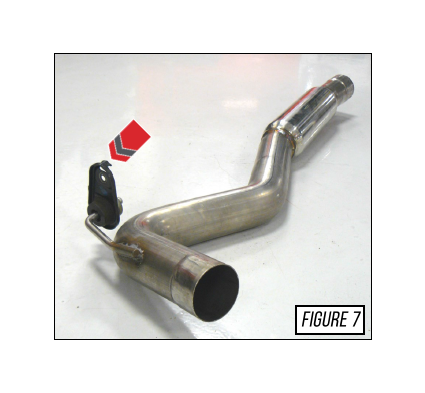
Transfer the OEM hanger bushing and bracket assemblies to the correlating AWE components.
The passenger side axle tube (part XJ) is shown with the factory hanger pre-installed by the arrow in Figure 7.
Be sure to maintain the original side and orientation, as the brackets are handed.
STEP 8:
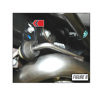
Install the axle tubes (parts XG & XJ) onto the H-pipe first then hang the pipe by the installed hanger bracket, as shown by the arrow in Figure 8. (part XJ shown)
Do not fully tighten any of the clamps or hanger brackets until the system is fully installed and adjusted.
STEP 9:
Pre-install two 3.0” Accu-Seal clamps onto the outlet portion of each axle section.
Install the driver rear section (part XK) and passenger rear section (part XL).
Tighten the exhaust hanger brackets into location with the 13mm socket.
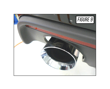
Install the exhaust tips with the included 3.0” T-Bolt clamp.
Center the exhaust tips within the valance, as shown in Figure 9. The AWE logo should be visible at the top edge; make adjustments as necessary.
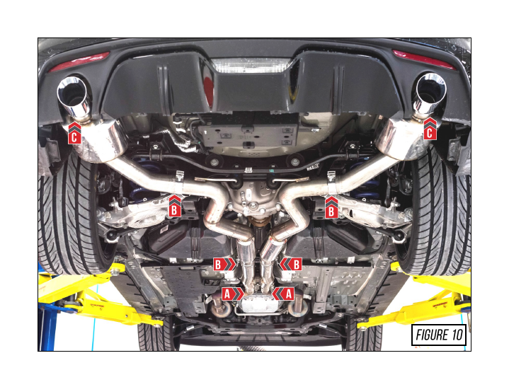
STEP 10:
Ensure the H-pipe section is level with the chassis. Tighten the factory sleeve clamps to the manufacturer’s recommended torque specifications, located by Arrow A in Figure 10.
Tighten the Accu-Seal clamp nuts to a minimum torque of 40 ft./lbs. or until secure with a 15mm socket, shown by Arrow B in Figure 10.
Check the tip alignment and secure the T-bolt clamp into location, as shown by Arrows C in Figure 10, with 7/16” or 11mm Socket. Tighten until the tip doesn’t move, then turn the bolt one (1) full turn.