FREE 1 to 3-Day Delivery on Orders $149+ Details
How to Install BMR Body Mounted Watts Links w/ Poly Bushings & Rod Ends - Hammertone on your Mustang
Tools Required
- Hydraulic jack and jack stands
- Wrenches and sockets: 15mm, 18mm, 19mm, 22mm, 9/16”, ¾”, 15/16”
- Small level

Shop Parts in this Guide
INSTALLATION:
1. Lift the rear of the vehicle and safely support with jack stands under the frame rails.
2. Using an 18mm wrench or socket, remove the panhard rod.
3. Using an 18mm wrench or socket remove the passenger side nut on the upper panhard rod support.
4. Using a 15mm socket, remove the (2) bolts on the driver side of the upper panhard rod support then remove the upper panhard rod support.
5. Using a 15mm wrench, remove the driver side sway bar end link bolt where it attaches to the frame.
6. Install the BMR cross-member using the existing mounting holes from the panhard rod and upper panhard rod support brace. Re-use the original mounting hardware for the driver side. On the passenger side use the provided 12mm x 110mm bolt and nut and 14mm x 100mm bolt and nut. Insert the supplied spacers on the inside of the mount as shown in IMAGE 1.
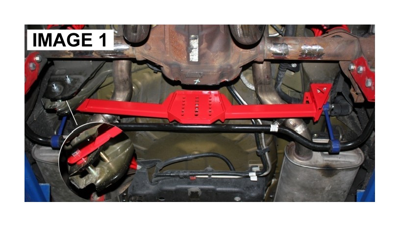
7. Torque the driver side 15mm bolts to 46 ft/lbs, the sway bar end link bolt to 85 ft/lbs., the passenger side upper bolt to 85 ft/lbs, and the passenger side lower bolt to 129 ft/lbs.
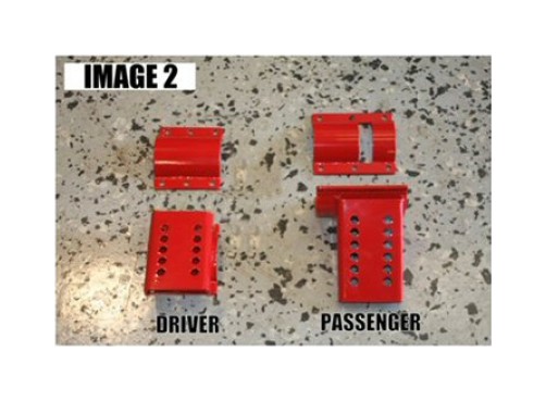
8. Locate the driver side axle clamp shown in IMAGE 2 and (6) 3/8”x1.25” bolts and nuts from the hardware packet.
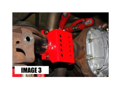
9. Bolt the axle clamp as far outward as possible on the driver side as shown in IMAGE 3. Snug the bolts but do not fully tighten yet.
10. Now locate the passenger side axle clamp shown in IMAGE 2 and (6) 3/8”x1” bolts and nuts from the hardware packet.
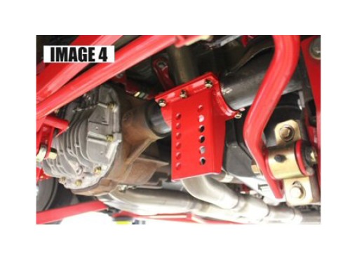
11. Bolt the axle clamp as far outward as possible on the passenger side as shown in IMAGE 4. The slot on the back side clamp is designed to clear the axle vent on top of the axle. Snug the bolts but do not fully tighten yet.
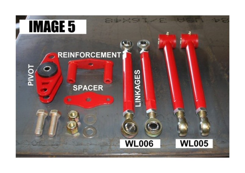
12. Gather the following components and hardware as shown in IMAGE 5 below:
Watts Link Pivot
Watts Link Spacer
Watts Link Reinforcement Bracket
Watts Linkages
(2) 5/8” x 2” bolts
(2) 5/8” stainless washers
(2) 5/8” lock nuts
(1) ½” x 3.5” bolt
(1) ½” poly-lock nut
(1) gold ½” flat washer
(2) 3/8” x 3.5” bolts
(2) 3/8” poly-lock nuts.
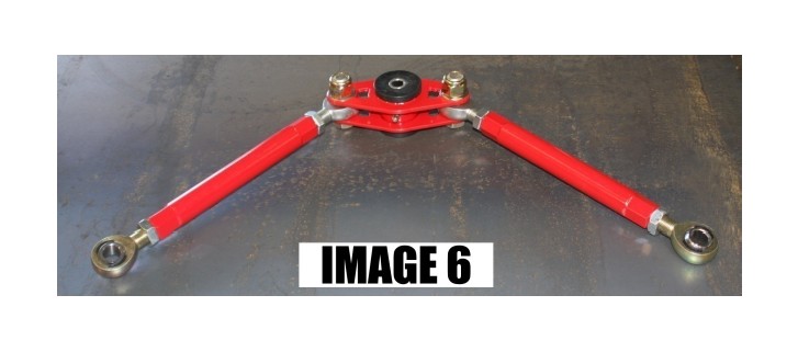
13. Mount the Watts Linkages to the Watts Link Pivot Assembly using the 5/8” bolts, washers, and lock nuts. Tighten the nuts with two 15/16” wrenches. (IMAGE 6)
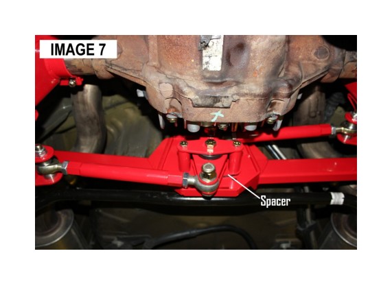
14. Choose a mounting hole for the Watts link pivot. Ride height and various other factors will determine the optimal mounting position but a good place to start on a slightly lowered car is somewhere around the middle. Bolt the Watts Link Pivot to the center of the cross-member as shown in IMAGE 7. Tighten the center ½” bolt to 80 ft/lbs with (2) ¾” wrenches and the outer 3/8” bolts to 35 ft/lbs with (2) 9/16” wrenches. NOTE: if you choose one of the upper holes to mount your Watts Link Pivot, the differential cover will interfere with the installation. There are two ways to proceed: Either lower the cross-brace to attach the Watts Link or remove the springs so you can compress the axle upwards to make clearance for the installation.
15. To determine the correct mounting points for the axle mounts it is necessary to simulate ride height. Lift the axle up with the jack until the frame just comes off the jack stands and the weight of the car is resting on the axle.
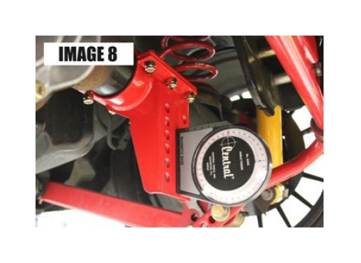
16. Now take your small level or angle finder and adjust the axle clamps to 90 degrees or true vertical as shown in IMAGE 8. Using a 9/16” wrench and socket, tighten all 6 bolts on each clamp in a criss-cross pattern, alternating between sides.
17. Locate the driver side axle mount as shown in IMAGE 9. Also gather (2) ½” x 1.5” bolts, (2) ½” stainless washers, and (2) ½” poly-lock nuts.

18. Bolt the axle mount to the axle clamp in the mounting holes that will position the link as horizontal as possible. Tighten the ½” bolts using (2) ¾” wrenches. (IMAGE 9)
19. Locate the remaining ½” x 3” bolts, ½” stainless washers, and ½” poly-lock nuts and connect the Watts Linkages to the outer Watts Link Mount placing the washer under the nut. Tighten bolts to 35 ft/lbs. NOTE: the Watts Links do not ship pre-adjusted. It is necessary to shorten/lengthen the links to fit them to each vehicle.
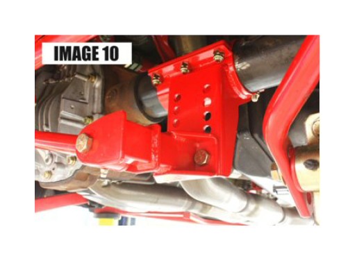
20. Duplicate steps 17-19 for the passenger side. (IMAGE 10)
21. Before tightening the jam nuts on the linkages, use a plumb bob or level to verify that the rear end is centered in the body. This may be accomplished by measuring the wheel’s position in reference to the wheel-well and comparing sides. If the rear-end is not centered, adjust the links to shift the body in the direction needed. For instance, if the rear-end is offset towards the drivers’ side ¼”, shorten the drivers’ side link 1/8” and lengthen the passenger side 1/8”.
22. Once centered, tighten the jam-nuts on the Watts Links using (2) 15/16” wrenches.
23. Use a grease gun to lube the center Watts pivot and outer poly bushings (WL005 only). Re-lube after a few hundred miles and then every other oil change.
24. Lower vehicle. An alignment is typically not necessary after this installation.