 FREE 1 to 3-Day Delivery on Orders $149+ Details
Differential Gears - Installation Instructions
Installation Time
4 hours
Tools Required
- Box/Open End Wrenchs - SAE and Metric
- Socket Sets - SAE and Metric
- Hammers - Hard and Soft Head
- Screw Drivers - Flat and Phillips
- Pliers - Adjustable and Needle Nose
- Pin Punch - Soft Punch
- 2 or 3 Jaw Gear Puller
- Bearing Puller
- Bar Tool * - (1" x 1/4" x 3" minimum bar stock)
- Pry Bars
- Torque Wrenches - (0 - 100 lb.-in) and (0-150 lb.-ft.)
- Hydraulic Press
- Dial Indicator and Setup Equipment
- Dial Caliper
- Lock Wire or Similar
- Gear Marking Compound
- Loctite "Red" Thread Locker or Equivalent
- Loctite "Blue" Thread Locker or Equivalent
- Permatex Gasket Making Material or Equivalent
- 80W-90 Premium Rear Axle Lubricant (Approx. 3.75 pts.)
- 4 ounces Ford Additive Friction Modifier for Traction-Lok axles
Shop Parts in this Guide
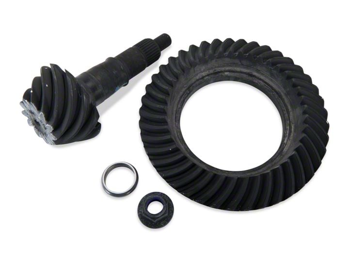
- Ford Performance Ring and Pinion Gear Kit; 3.73 Gear Ratio (11-14 Mustang V6; 86-14 V8 Mustang, Excluding 13-14 GT500)
- Ford Performance Ring and Pinion Gear Kit; 4.10 Gear Ratio (11-14 Mustang V6; 86-14 V8 Mustang, Excluding 13-14 GT500)
- Motive Gear Performance Ring and Pinion Gear Kit; 3.55 Gear Ratio (11-14 Mustang V6; 86-14 V8 Mustang, Excluding 13-14 GT500)
Installation
1. When changing gears in a vehicle with high mileage (60,000 ), it is suggested that the bearings also be swapped. That is what this install will be showing as well.
2. First item of business is to disconnect the negative cable of the battery, so as to not accidentally set off safety features such as air bags, etc. while working.
3. Securely support the car on jack stands, or preferably on a lift.
4. Remove the five lower differential cover bolts and loosen the five upper bolts, allowing you to softly tap the bottom edge of the cover, opening it up “clam shell style”. Empty the lube into a container below. The sway bar must also be removed or lowered, to gain complete access to the gears, as shown in Fig. 1

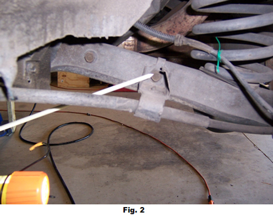
5. Remove both rear wheels, giving access to the two sway bar bolts on each side. Carefully remove the anti-lock sensing cable from its retainer and twist tie it out of the way, preferably to one of the spring coils, as shown in Fig. 2. Remove three sway bar bolts and loosen the fourth, allowing the bar to be lowered and wired in place just out of the way.
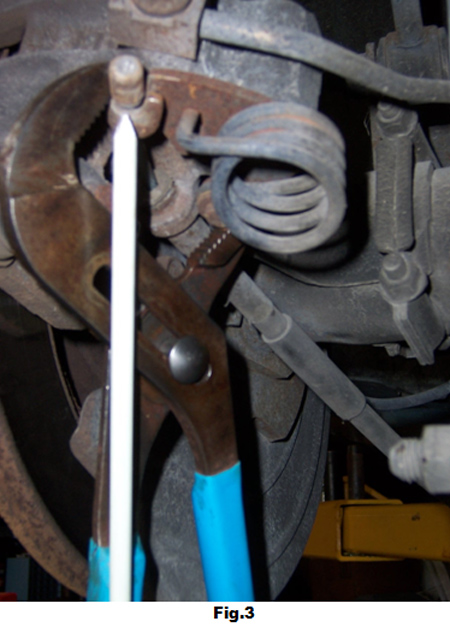
6. Using adjustable pliers, squeeze together the parking brake lever and remove the brake cable from the retainer and the “C” ring from the cable, as shown in Fig. 3 and Fig. 4.

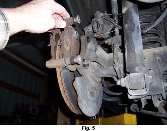
7. If you are planning to replace brake pads, then the two caliper retaining pins should now be removed. Otherwise, the two caliper support bracket bolts should be removed as shown in Fig. 5, and carefully suspended out of the way so as to not stress the flexible brake hose.
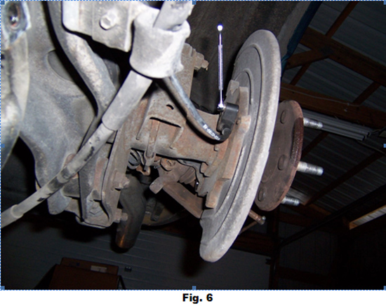
8. Remove the brake rotor from the axle studs and the anti-lock sensor magnetic pickup from the brake adapter flange, as shown in Fig. 6.
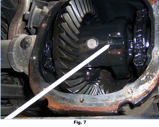
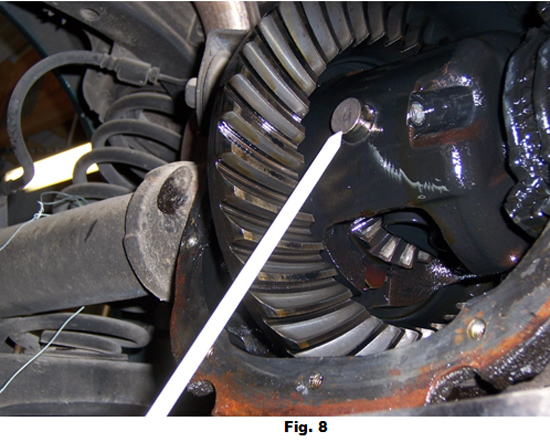
9. Back at the differential, remove the differential pinion shaft lock pin and then the shaft, as shown in Fig. 7 and Fig. 8.
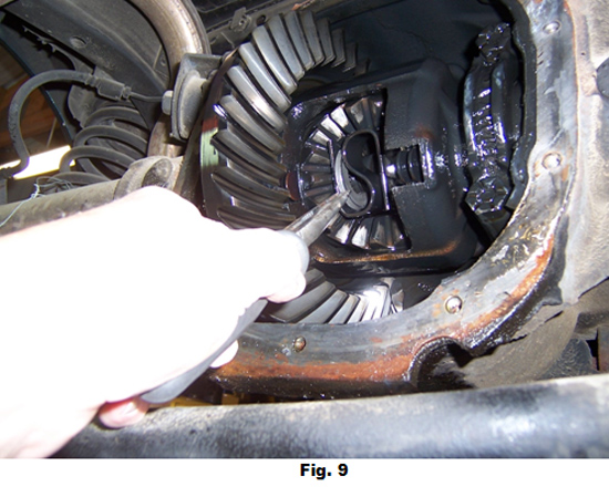
10. Rotate the differential and push both axle shafts in, toward the center of the differential, allowing the removal of the retaining “U” washers as in Fig. 9. Carefully remove each axle, so as not to damage the outer bearings or oil seals.
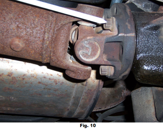
11. Before removing the drive shaft, etch or scribe a mark on the mating parts to allow proper re-assembly as in Fig. 10. The four bolts holding the drive shaft to the rear axle U-joint flange can be removed by inserting a pry bar between spaces in the U-joint to secure the drive shaft. The drive shaft can be supported out of the way by a bar or pipe, placed on the top side of the mufflers.
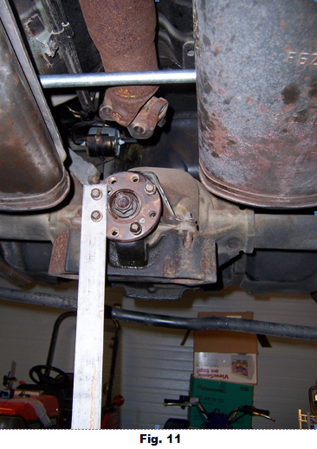
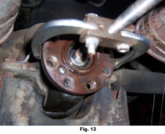
12. Remove the rear axle U-joint flange by first fabricating a (Bar Tool) * out of bar stock with two holes drilled near one end, that will match up to the threaded holes in the flange as shown in Fig 11. Use this tool to help remove the pinion nut (save this nut for later use). The bar tool will also later help hold the new pinion tight when taking backlash measurements. A 2 or 3 - jaw gear puller will now remove the flange as in Fig. 12.
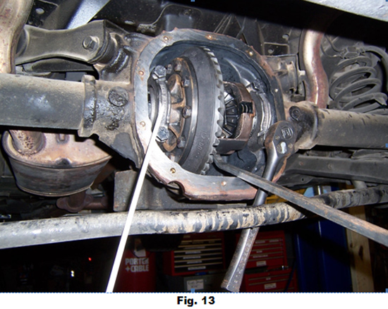
13. Remove the two bolts from each bearing cap and take note of the orientation of the arrows, cast into each cap as shown in Fig. 13. It is important to return the caps and shims as originally found upon rebuild. After bolt removal, carefully pry the entire differential case away from the bearing pockets and out of the housing (save and mark the caps and shims as per left and right side). Have another person prepared to help ease the unit out, as it is very heavy! The pinion and attached large bearing can now be removed from this end of the housing.
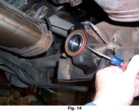
14. Remove pinion oil seal from front end of housing by carefully lifting seal flange away from housing, by tapping a chisel or thin blade screw driver around entire seal as in Fig. 14. The front end parts of the pinion assembly (collapsible spacer, small bearing, and oil slinger) can now be removed (save these parts for later use).
15. All parts, including the housing, can now be cleaned and inspected.
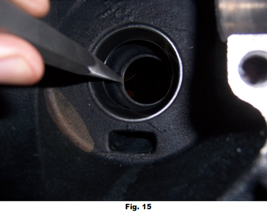
16. Remove the two pinion bearing races that are pressed into the housing by using a pin punch or similar device to carefully tap each out (one from each side), as in Fig. 15. The new bearing races from the bearing kit can be installed in a similar manner, after the bores have been cleaned and inspected for nicks or scratches. The races must be tapped in securely with no gaps to insure proper bearing alignment.
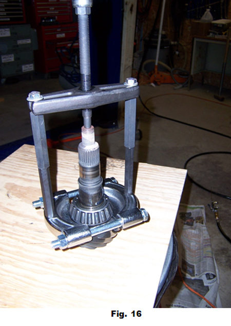
17. Old bearings can be removed from the pinion and differential case by removal tool or hydraulic press, as in Fig. 16. Save the shims found underneath the pinion bearing, as they may be reused with the new bearing set.
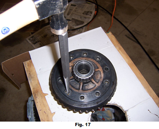
18. Remove the ring gear bolts and separate the gear from the differential case by tapping on alternate sides with a punch, as shown in Fig. 17.
19. After cleaning and inspecting the mating surfaces of the differential case and the new ring gear, they can be assembled and a drop or two of red Loctite thread locker or equivalent applied to each bolt and tightened in a criss-cross pattern, then finally torqued to 70-84 Lb.-ft.
20. Reassembly is started by putting the original pinion shims onto the new pinion and pressing the new bearing securely onto the shaft. After lightly lubricating the bearing surfaces, install the pinion from the back side of the housing. While holding it in place, install the old collapsible spacer, new bearing, oil slinger and rear axle U-joint flange from the front side.
21. Tighten them together securely with the old pinion nut, so there is no looseness in the bearings. This is being done to allow the testing for gear backlash and proper gear pattern, without ruining the new collapsible spacer or pinion nut.
22. With the new bearings pressed onto the differential case and lightly lubricating all bearing surfaces, install the unit with the original left side shims.
23. Attempt to insert the right side shims. If right side shims are either too tight or too loose, use a combination of shims supplied in the kit to obtain the tightest fit possible.
24. Attach the bearing caps securely and rotate the assembly by turning the U-joint flange. Attach the bar tool to the rear axle U-joint flange and secure the other end to a part of the frame holding the pinion motionless.
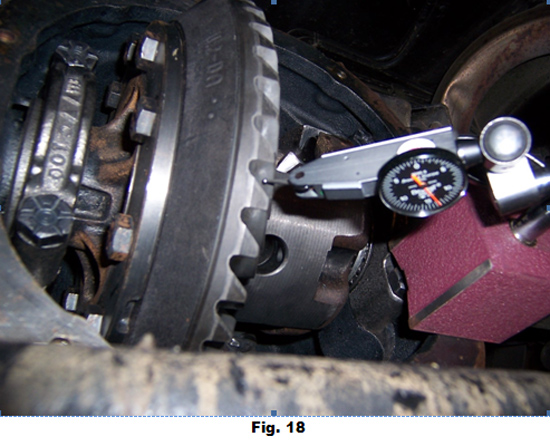
25. Using a magnetic base or other fixture, locate the dial indicator bar parallel to and just touching the underside of a ring gear tooth. Rock the ring gear back and forth and observe the amount of movement as shown in Fig. 18. The total movement should be.008 -.015 with the ideal being.012 -.015.
26. If the backlash is too small, decrease the shim thickness on the left side of the differential and increase the same amount on the right side. If backlash is too large, increase the shim thickness on the left side and decrease a like amount on the right side. A.006 shim adjustment will produce approximately a.004 change in backlash.
27. To check for proper tooth contact pattern, apply an even coat of white or yellow marking compound to the convex side (the forward-drive side) of three or four ring gear teeth.
28. While putting pressure on the ring gear with a heavily gloved hand (this done to allow the mating teeth to make an impression in the marking compound and to protect your hand from being injured by sharp parts of the gear) turn the rear axle U-joint flange in the direction that would make the car go forward, enough times to allow the pinion to rotate through the marking compound two or three times. This will leave an imprint in the compound that will indicate where the mating teeth are contacting, as shown in Fig. 19.
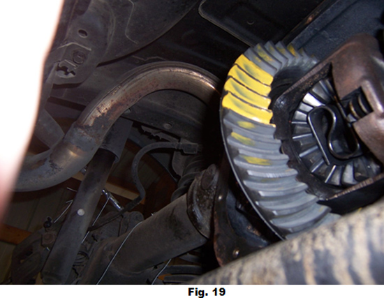
29. A good pattern is one that shows the contact mid-way between the inner and outer diameter (toe and heel) of the ring gear and mid-way between the top and bottom (tip-to-root) of each tooth. This pattern is important to insure the strongest gear set possible.
30. The adjustment is made by adding or removing shim thickness from under the pinion bearing that is pressed onto the pinion gear. If the wear pattern is too close to the outside diameter (heel) of the gear, add shim thickness. If too close to the inside diameter (toe) of the gear, remove shim thickness. Do this in relatively small increments (.002 -.004 shims), so as not to over move the pattern. This will require removal of the differential case and the entire pinion assembly, removing the large pinion bearing, adjusting the shim amount, re-pressing the bearing, cleaning all of the marking compound from all teeth and re-assembling and retesting as above.
31. Once the proper pattern is reached, the differential and pinion assembly are again removed, cleaned and the bearings coated with some of the new gear lube to be added later and re-assembled.
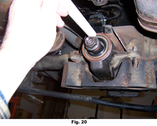
32. This time the pinion will be assembled using the NEW collapsible spacer, but just hand tighten the old pinion nut, so it just holds all the parts in place while you install the oil seal. Carefully tap the seal all around the edge with a soft punch, as not to cock or damage the metal ring, as in Fig. 20.
33. Remove the old pinion nut, clean the pinion threads thoroughly and carefully apply premium grease to the lips of the seal. Carefully insert the rear axle U-joint flange over the lips of the seal.
34. Attach the Bar Tool to the flange, apply a light coating of oil to the washer surface of the nut and start tightening the NEW pinion nut. The nut will go on hard and the Tool will help you hold the flange. Go slowly, as you get close to taking the slack out between the two bearings.
35. Two numbers are very important in the tightening process. You want to be exerting at least 140 Lb.-ft. of torque on the nut while tightening. Put a torque wrench on just before the bearing slack is gone. The new nut and clean/dry pinion threads should accomplish this.
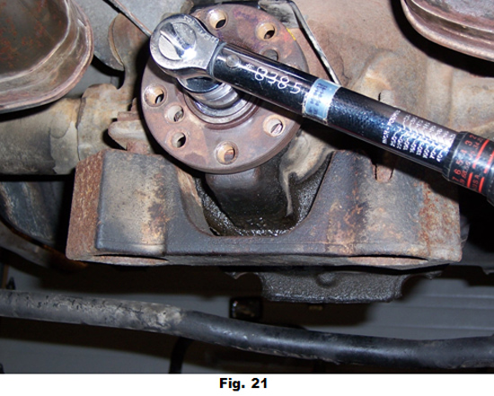
36. A pinion shaft with new bearings needs to have a preload of 16-28 lbs-in. Once the slack is gone between the bearings, drag or preload will start to build up on the pinion. Care must be taken not to go too fast on the tightening at this stage, so as not to exceed the 16-28 lbs-in. of torque. Constant checking with a torque wrench should be done, as in Fig. 21.
Note:If too much preload is applied, you cannot back the nut off, as the collapsible spacer has been set. If this happens, you must disassemble the pinion assembly and re-assemble with another NEW collapsible spacer and probably NEW nut.
37. Re-assemble the differential case making a last check for a tight fit between shims and adding any additional shims to the right side. Re-install the bearing caps in their proper orientation and add a couple drops of red Loctite thread locker to each bolt. Tighten in a crossing pattern to 76-89 lbs-ft. of torque.
38. Re-install the axles by first applying premium grease to the lips of the seals and carefully inserting the axles, so as not to damage the seal or bearing with the splined end of the axle.
39. Push the axles in toward the center of the differential as far as possible, in order to expose the slot on the inner end. There should also be an O-ring in that slot to help hold the “U” washer in place. Install the “U”washers as far in as they will go, as shown in the example in the disassembly stage, Fig. 9.
40. When properly installed, you should be able to now pull the axles back away from the differential center and they should lock the “U” washers back into a counter-bore, preventing them from removal. That will allow enough space to insert the differential pinion shaft, orienting it as was shown at removal in Fig. 8.
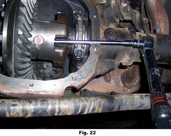
41. Once in flush to the case, the differential pinion shaft lock pin can be installed with a drop of red Loctite thread locker and tightened to 15-30 lbs-ft. of torque, as in Fig. 22.
42. After making sure the mating surfaces of the cover are clean, dry and free of nicks and scratches, apply a 1/8” bead of Permatex gasket making material or equivalent around the entire cover and around each bolt hole. Apply a drop of blue Loctite thread locker to each bolt and tighten in a criss-cross pattern to 28-38 lbs-ft. of torque.

43 .If you have a Traction-Loc differential and are using a gear lube that doesn’t already contain a friction modifier, add 80W-90 weight premium gear lube to within ¼ to ½ inch of the bottom edge of the filler hole. Then add a 4ounce bottle of Ford Additive Friction Modifier. Otherwise, fill just to the bottom edge of the filler hole and torque the plug to 15-30 lbs-ft.
44. Inspect the mating surfaces of the rear axle U-joint flange and the rear end of the drive shaft and remove any nicks and scratches. Align the scribe marks on each and install each bolt with a couple drops of blue Loctite thread locker and torque to75-90 lbs-ft., as shown in Fig. 10.
45. Clean the magnetic probe of the antilock sensor pickup and install into brake adapter flange by applying a drop of blue Loctite thread locker to the bolt and torque to 40 -60 lbs-in., as shown in Fig. 6.
46. Slide the brake rotors on and attach the caliper support bracket with a couple drops of blue Loctite thread locker to each bolt and torque to 65-87 lbs-ft., as in Fig. 5.
47. Insert the parking brake cable into the retaining hole and secure it by sliding the “C” ring into place, as shown in Fig. 4.
48. Squeeze the parking brake lever together and insert the end of the cable into the retaining loop, as in Fig. 3.
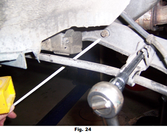
49. Reconnect the four sway bar bolts, making sure the brake cable support brackets are properly located and torqued to 35-41 lbs-ft., as shown in Fig. 24. Attach the antilock brake cable into its retaining slot.
50. Remount the rear tires and torque to 85-104 lbs-ft.
51. Lower vehicle, reattach the negative cable to the battery and test drive.
Installation instructions provided by AmericanMuscle Customer Thomas A. Skoumal 1.28.09

