 FREE 1 to 3-Day Delivery on Orders $149+ Details
How to Install a Ford Racing High Performance Dual Fuel Pump Kit on Your 2005-2009 Mustang GT
Installation
NO PART OF THIS DOCUMENT MAY BE REPRODUCED WITHOUT PRIOR AGREEMENT AND WRITTEN PERMISSION OFFORD RACING PERFORMANCE PARTS
Please contact the Techline for the most current instruction information (800) FORD788
! ! ! PLEASE READ THE FOLLOWING INSTRUCTIONS CAREFULLY PRIOR TO INSTALLATION ! ! !
OVERVIEW:
The following information describes the procedure for the installation of the M-9407-GT05 dual fuel pump kit into 2005-07 Mustang GT.
! ! ! WARNING: DO NOT SMOKE OR CARRY LIGHTED TOBACCO OR OPEN FLAME OF ANY TYPE WHEN WORKING ON OR NEAR ANY FUEL-RELATED COMPONENT. HIGHLY FLAMMABLE MIXTURES ARE ALWAYS PRESENT AND MAY BE IGNITED, RESULTING IN POSSIBLE PERSONAL INJURY ! ! !
! ! ! WARNING: FUEL IN THE FUEL SYSTEM REMAINS UNDER HIGH PRESSURE EVEN WHEN THE ENGINE IS NOT RUNNING. BEFORE SERVICING OR DISCONNECTING ANY OF THE FUEL LINES OR FUEL SYSTEM COMPONENTS, THE FUEL SYSTEM PRESSURE MUST BE RELIEVED TO PREVENT ACCIDENTAL SPRAYING OF FUEL, RESULTING IN PERSONAL INJURY OR A FIRE HAZARD ! ! !
! ! ! WARNING: DO NOT CARRY PERSONAL ELECTRONIC DEVICES SUCH AS CELL PHONES, PAGERS OR AUDIO EQUIPMENT OF ANY TYPE WHEN WORKING ON OR NEAR ANY FUEL-RELATED COMPONENTS. HIGHLY FLAMMABLE MIXTURES ARE ALWAYS PRESENT AND MAY BE IGNITED. FAILURE TO FOLLOW THESE INSTRUCTIONS CAN RESULT IN PERSONAL INJURY ! ! !
! ! ! WARNING: THIS PROCEDURE INVOLVES FUEL HANDLING. BE PREPARED FOR SPILLAGE AT ALL TIMES AND ALWAYS OBSERVE FUEL HANDLING PRECAUTIONS. FAILURE TO FOLLOW THESE INSTRUCTIONS CAN RESULT IN PERSONAL INJURY ! ! !
! ! ! WARNING: FUEL LEVEL MUST BE AT ¾ OF A TANK OR LOWER OR FUEL SPILLAGE WILL OCCUR WHEN FUEL MODULE IS REMOVED ! ! !
STEP 1:Release fuel system pressure.
1A: The fuel pump relay can be found in the bussed electrical center. The fuel pump relay is located in position 21 as shown in the inside cover of the bussed electrical center. Remove the fuel pump relay (see Fig. 1).
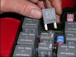
Fig. 1
1B: Start the engine and allow it to idle until it stalls. If engine does not start, proceed to STEP 1D.
1C: After the engine stalls, crank the engine for approximately 5 seconds to make sure the fuel injection supply manifold pressure has been released.
1D: Turn the ignition switch to the OFF position.
! ! ! WARNING: BATTERIES NORMALLY PRODUCE EXPLOSIVE GASES. THEREFORE, DO NOT ALLOW FLAMES, SPARKS OR LIGHTED SUBSTANCES TO COME NEAR THE BATTERY. WHEN CHARGING OR WORKING NEAR A BATTERY, ALWAYS SHIELD YOUR FACE AND PROTECT YOUR EYES. ALWAYS PROVIDE VENTILATION. FAILURE TO FOLLOW THESE INSTRUCTIONS MAY RESULT IN PERSONAL INJURY ! ! !
! ! ! WARNING: KEEP OUT OF THE REACH OF CHILDREN. BATTERIES CONTAIN SULFURIC ACID. AVOID CONTACT WITH SKIN, EYES OR CLOTHING. ALSO, SHIELD YOUR EYES WHEN WORKING NEAR THE BATTERY TO PROTECT AGAINST POSSIBLE SPLASHING OF THE ACID SOLUTION. IN CASE OF ACID CONTACT WITH THE SKIN OR EYES, FLUSH IMMEDIATELY WITH WATER FOR A MINIMUM OF 15 MINUTES AND GET PROMPT MEDICAL ATTENTION. IF ACID IS SWALLOWED, CALL A PHYSICIAN IMMEDIATELY. FAILURE TO FOLLOW THESE INSTRUCTIONS MAY RESULT IN PERSONAL INJURY ! ! !
STEP 2:Disconnect battery ground terminal (see Fig. 2).
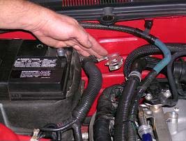
Fig. 2
STEP 3:The fuel level in the tank should be ¾ of a tank or less before proceeding. If fuel exceeds more than ¾ of a tank, then follow STEPS 4-6. If fuel level is ¾ of a tank or less, then proceed to STEP 7.
STEP 4:Remove the fuel tank filler cap.
STEP 5:Insert a suitable drain hose into the fuel tank filler pipe until it reaches the fuel tank inlet tube.
CAUTION! The fuel pump and fuel level sensor will be below the fuel level in the tank when the tank is full. Make sure to drain ¼ of the fuel capacity through the filler pipe prior to removing the pumps or fuel spillage will occur.
STEP 6:Attach the fuel storage tanker to the fuel drain hose and remove as much fuel as possible from the fuel tank filler pipe. The fuel tank has a 16-gallon capacity. The removal of 4 gallons would lower the fuel level ¼ of a tank.
STEP 7:Remove the rear seat bottom and any insulation padding covering the fuel pump access cover.
7A: From under the front of the rear cushion assembly, push in the seat cushion release tab located on the left and right of the seat, lift and remove the rear cushion assembly (see Fig. 3).
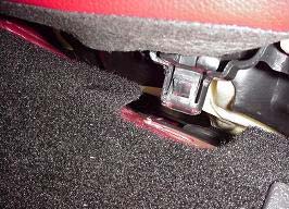
Fig. 3
STEP 8:Remove the fuel pump access cover (see Fig. 4).
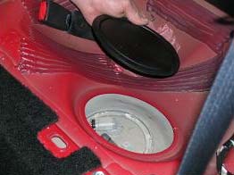
Fig. 4
STEP 9:Disconnect the fuel pump electrical connector (see Fig. 5).
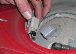
Fig. 5
CAUTION! If the liquid or vapor tube is damaged (torn, holes or delaminated), the effected tube assembly must be replaced with a new tube assembly. Do not use aftermarket sleeving. Do not re-adhere loose sleeving material.
CAUTION! When reusing liquid or vapor tube connectors, make sure to use compressed air to remove any foreign material from the connector retaining clip area before separating from the tube. Apply clean engine oil to the end of the tube before inserting the tube into the connector.
CAUTION! Fuel injection equipment is manufactured to very precise tolerances and fine clearances. It is therefore essential that absolute cleanliness be observed when working with these components. Always install blanking plugs to any open orifices or tubes.
STEP 10:Disconnect the fuel tube quick connect coupling on the fuel pump.
10A: Press the fuel tube quick connect coupling button and pull the fuel tube to disconnect (see Fig. 6).
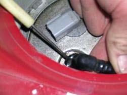
Fig. 6
STEP 11:Using a fuel tank lock ring wrench or a brass punch, remove the fuel pump retaining lock ring(see Figs. 7-8)
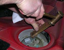
Fig. 7
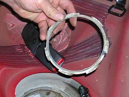
Fig. 8
CAUTION! The fuel pump must be handled carefully to avoid damage to the float arm, filter and convolute hoses.
STEP 12:Carefully lift the fuel pump out of the fuel tank enough to access and release the fuel cross-over tube quick connect coupling from the fuel pump (see Fig. 9).
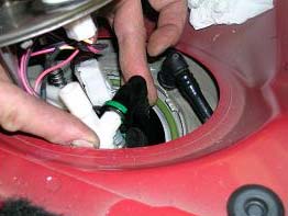
Fig. 9
STEP 13:Completely remove the fuel pump from the fuel tank (see Fig. 10).
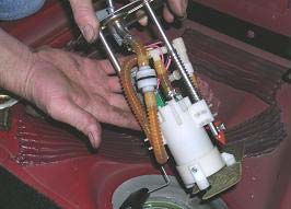
Fig. 10
CAUTION! Inspect the surfaces of the fuel pump mounting flange and fuel tank O-ring seal contact surfaces. Do not polish or adjust the O-ring seal contact area of the fuel tank flange or the fuel tank. Install a new fuel tank if the O-ring seal contact area is bent, scratched or corroded.
CAUTION! Make sure to install a new fuel pump O-ring seal and lock ring.
STEP 14:To install, apply clean engine oil to the O-ring seal.
STEP 15:Install new fuel pump O-ring seal (see Fig. 11).
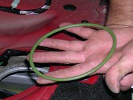
Fig. 11
STEP 16:Position the dual fuel pump into the fuel tank.
STEP 17:Connect the cross-over fuel tube quick connect coupling to the fuel pump.
CAUTION! Make sure the fuel tube clicks into place when installing the tube. To make sure that the fuel tube is fully seated, pull on the tube.
STEP 18:Make sure the alignment arrows on the dual fuel pump and the fuel tank meet before tightening the dual fuel pump lock ring. Using the special tool or brass punch, install the dual fuel pump with the new lock ring.
18A: Tighten the lock ring until it meets the stops on the fuel tank.
NOTE: The fuel pump is spring-loaded into the tank and may require slight pressure to install lock ring.
STEP 19:/ Connect the quick connect coupling on top of the dual fuel pump.
CAUTION! Make sure the fuel tube clicks into place when installing the tube. To make sure that the fuel tube is fully seated, pull on the tube.
STEP 20:Remove black cover from inside trunk to access fuel pump driver module (see Fig. 12).
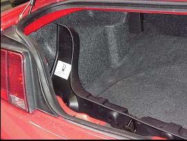
Fig. 12
STEP 21:Disconnect fuel pump driver module located in spare tire well on driver side (see Fig. 13).

Fig. 13
STEP 22:Mount additional fuel pump driver module in spare tire well on opposite side of existing fuel pump driver (see Fig. 14).
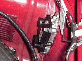
Fig. 14
STEP 23:Mount RELAY from harness on inside of tire well to the left of the stock fuel pump driver module(see Fig. 15).

Fig. 15
STEP 24:Connect connector labeled FPDM BODY SIDE CONNECTOR into the harness where the existing fuel pump driver module was connected.
STEP 25:Connect connector labeled FPDM NO. 1 to stock fuel pump driver module.
STEP 26:Mount wires labeled RELAY GROUND and FPDM NO. 1 GROUND in hole next to stock ground using ground screw (see Fig. 16).
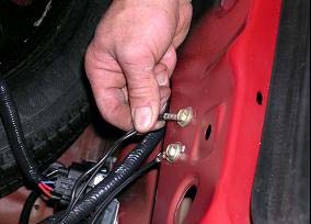
Fig. 16
STEP 27:Connect connector labeled FPDM NO. 2 to newly mounted fuel pump driver module on passenger side.
STEP 28:Mount wire labeled FPDM NO. 2 GROUND to stock ground for audio amp on passenger side (see Fig. 17).
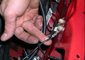
Fig. 17
STEP 29:Run connectors labeled DUAL PUMP CONNECTOR and SENDER CONNECTOR along the wall of the driver side of trunk, under rear seat and into rear seat area where the dual pump is located.
29A: For 2005 Mustang GT, a 1½” diameter hole will need to be cut out in the center of the access cover for the fuel pump (see Fig. 18). Once hole is cut out, pull DUAL PUMP CONNECTOR and SENDER CONNECTOR (1) through hole and seal hole with grommet. Unlock existing 4-pin female connector on the harness previously connected into the stock fuel pump. Unlock the connector by pulling the blue center piece forward (see Fig. 19). Proceed to STEP 29C.
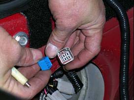
Fig. 19
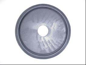
Fig. 18
29B: For 2006 Mustang GT and beyond, a second hole with a 1½” diameter will need to be cut into the access cover. The hole should be ½” away from existing hole to allow clearance for the new grommet to seal. Once the hole is cut out, pull DUAL PUMP CONNECTOR and SENDERCONNECTOR (1) through hole and seal hole with grommet. Do not take the existing harness out of the existing hole in the access cover. Unlock the existing 4-pin female connector (connector on the end of the existing harness going through access cover) previously connected into the stock fuel pump. Unlock the connector by pulling the blue center piece forward (see fig. 19).
29C: Release terminals for the LB/YE wire and the LG/VT wire from the connector housing. Do not remove terminal from wire. These are the fuel sender wires.
STEP 30:Insert fuel sender wires into the connector labeled SENDER CONNECTOR (2) with the LB/YE wire going into the left side and the LG/VT wire going into the right (see Fig. 20).
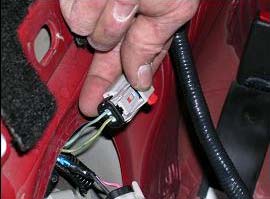
Fig. 20
STEP 31:Connect SENDER CONNECTOR (1) into SENDER CONNECTOR (2). Once connection is made, the LG/VT wire should line up with the RD/YE wire and the LB/YE with the BK wire.
STEP 32:Connect the DUAL PUMP CONNECTOR to the newly installed dual pump.
STEP 33:Install access cover (see Fig. 21 – 2005 Mustang GT view).
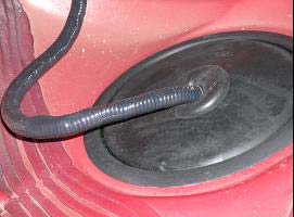
Fig. 21
STEP 34:Run wire labeled FUSE/POWER (1) along the trunk wall, into the back seat of the passenger side, and along the wire track on the passenger side of the vehicle (see Figs. 22-24).
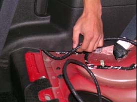
Fig. 23
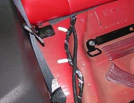
Fig. 22
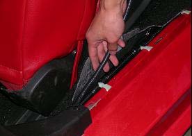
Fig. 24
34A: A hole will need to be placed in the grommet located in the lower area of the front wall on the passenger side in order to run the wire through (see Fig. 25).
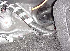
Fig. 25
STEP 35:Lift vehicle and remove the right front tire from vehicle along with the rear fender well cover. Continue to run wire along existing wire harness in fender well using wire ties to secure the wire along the existing wire harness (see Fig. 26).
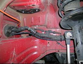
Fig. 26
STEP 36:Remove innermost fastener on front fender well cover and continue to run wire into engine compartment. The wire should come through the hole located near the washer fluid neck (see Figs. 27-28).
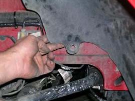
Fig. 27
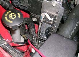
Fig. 28
STEP 37:Connect FUSE/POWER (1) to FUSE/POWER (2).
STEP 38:Connect POWER to hot side of bussed electrical center (see Fig. 29).
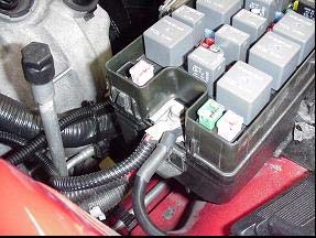
Fig. 29
STEP 39:Reinstall relay in position 21 of bussed electrical center.
STEP 40:Connect negative terminal of battery.
STEP 41:Check for leaks before starting the engine.
NOTE: It may take more than one key cycle to pressurize the fuel system. Cycle the ignition key and wait 3 seconds to pressurize the fuel system.
STEP 42:Start the engine and check for leaks.
Techline (800) FORD788
Factory Ford shop manuals are available from Helm Publications, 1-800-782-4356

