 FREE 1 to 3-Day Delivery on Orders $149+ Details
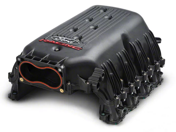
How to Install a Ford Racing Intake Manifold for a 2005-2010 Mustang GT
Installation Time
2 hours
Tools Required
- Flathead Screwdriver
- 5/8" Fuel Line Disconnect Tool
- 8mm Deep Socket
- 10mm Socket
- 5mm Hex Key
- Drill and 1/4" Drill Bit
- Torque Wrench (Inch per Pound)
- Box Cutter or Razor Blade
- Panel Removal Tool (Optional)
Shop Parts in this Guide
Installation
Step 1 (Depressurize the Fuel System)
You need to depressurize the fuel system by disconnecting the Fuel Pump Driver Module (FPDM). This can be found in the spare wheel well in the trunk.
After the Module has been disconnected start the car and run until it stalls and then crank the engine for an additional 10 seconds. Note your car may or may not start.
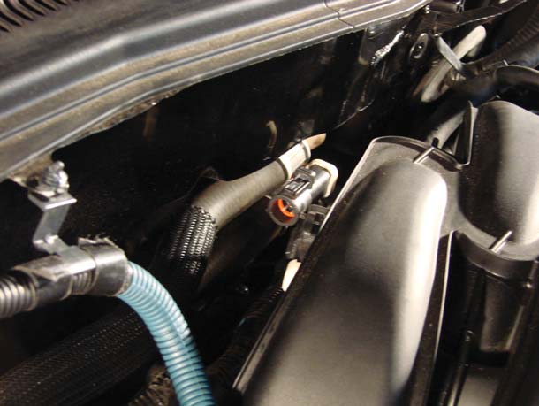
Step 2 (Disconnect Electrical & Vacuum Connections Remove Intake)
Disconnect the following electrical and vacuum connections found in the engine bay:
A. Negative Terminal on the Battery (8mm Socket)
B. Throttle Position Sensor (TPS)
C. Mass Air Flow Sensor (MAF
D. Electric Throttle Connection (ETC)
E: CMCV (Charge Motion Control Valves) -- Located behind the Manifold the CMCV connector has a push-in retainer that needs to be removed from the bracket with a panel-popper tool. This connection does not get used with the new intake manifold.
F. FPS (Fuel Pressure Sensor)
G. Fuel Injector Connections (4 on each side of the Intake Manifold)
H. Vacuum A - E
I. Remove your intake box or filter. If you have the stock intake use a flathead screwdriver to loosen the connections.
NOT ALL ARE PICTURED BELOW!!!!


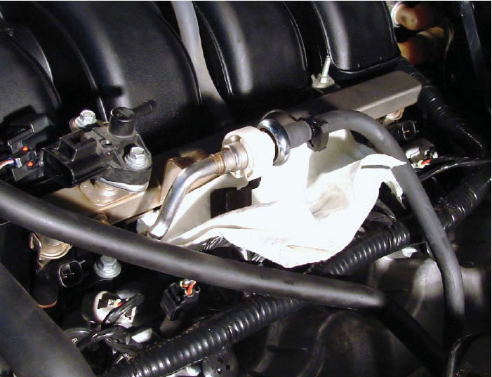
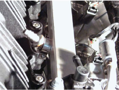
Step 3: (Disconnect Fuel Line and Remove Fuel Rails)
Use a 5/8" Fuel Line Quick Disconnect tool and disconnect the fuel line. Place rags or towels under the connection as there will still be fuel in the lines and it will leak. Also wear goggles in case there is still some pressure within the fuel lines.
Remove the two bolts holding the fuel rails using an 8mm Deep Socket. After the bolts have been removed remove the fuel rail with fuel injectors still connected
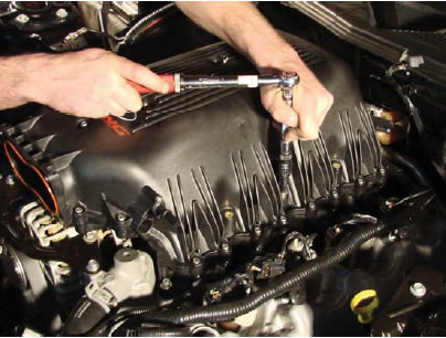
Step 4: (Remove the Throttle Body)
Remove the throttle body from the Intake Manifold using an 8mm socket for the top two bolts and a 10mm socket for the bottom two bolts.
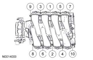
Step 5 (Unbolt and remove the Intake Manifold)
Unbolt the Intake Manifold using a 10mm deep socket. There are 10 bolts holding the manifold in place and they need to be removed in correct sequence. Follow the sequence below.
| 4 | 1 |
| 6 | 7 |
| 10 | 9 |
| 8 | 5 |
| 2 | 3 |
Front of the Car
After all bolts have been removed remove the Intake Manifold and set aside.
Step 6: (Modify the Alternator Bracket)
Remove the Alternator Bracket using an 8mm and 10mm socket.
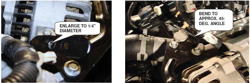
After Removing Bracket. Enlarge the bottom hole using 1/4" drill bit. After enlarging the hole reattach the bracket and torque to 89lb per inch. You will need to bend the tab forward about 45 degrees to allow clearance for alternator wire.
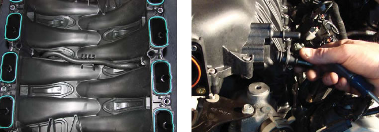
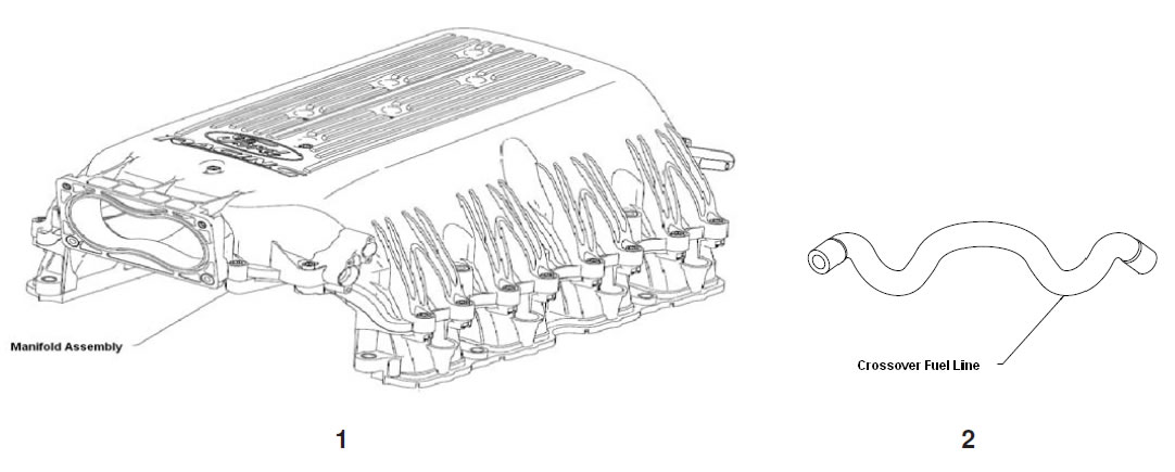
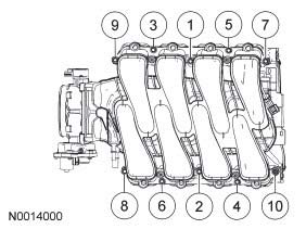
Step 7 (Install Intake Manifold)
Route the supplied fuel line crossover on the underside of the manifold. Install the manifold and hand tighten with new supplied bolts. The new bolts will require a
5mm Hex Key and will need to be tightened to 89lb per inch following the sequence below.
| 7 | 10 |
| 5 | 4 |
| 1 | 2 |
| 3 | 6 |
| 9 | 8 |
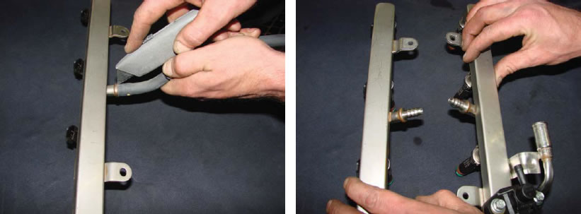
Step 8 (Modify and Reattach Fuel Rail)
Cut the fuel line crossover from the fuel rail using a razor and discard.
Reconnect fuel rails by pushing gently on fuel injectors to ensure they are seated. Attach new crossover line to fuel rail an d used the supplied clamps. The clamps can be tightened with a flathead screwdriver
Step 9 (Shorten Vacuum Tube)
The vacuum tube connecting the intake manifold to the valve cover on the driver's side will need to be shortened by 1.5". Start by cutting the insulating cover and by 1.5" but do not cut through to the plastic tube. Peel back cover.
Measure 1.5" from the beginning of the tube but not from the connector and cut tube. Remove the connector and reattach by heating the end of the tube with a heat gun or hairdryer. The tube will shrink around the connector as it cools.
Step 10 (Reattach all electrical and vacuum connections) Reattach :
A. Throttle Position Sensor (TPS)
B. Mass Air Flow Sensor (MAF)
C. Electric Throttle Connection (ETC)
D. FPS (Fuel Pressure Sensor)
E. Fuel Injector Connections (4 on each side of the Intake Manifold)
F. Vacuum A - E
G. Air Filter
H. Negative Terminal on the Battery (8mm Socket)
I. FPDM
Start the car and check for leaks. Load new tune. DO NOT DRIVE UNTIL YOU HAVE A TUNE!
Related Guides
-
Installation
-
Installation
-
Installation

