 FREE 1 to 3-Day Delivery on Orders $149+ Details
How to Install a Ford Racing 8.8 Rear Axle Bearing & Seal Kit on your 1986-2004 Mustang; Excludes IR
Installation Time
4 hours
Tools Required
- Box/Open End Wrenches - SAE & Metric
- Socket Sets – SAE & Metric
- Hammers – Hard & Soft head
- Screwdrivers
- Chisel
- Pliers – Adjustable & Needle nose
- Slide hammer or 2 jaw pullers
- Pry Bars
- Bearing and seal installer or Equivalent
- Torque Wrenches – (0 – 100 lb.-in) & (0-150 lb.-ft.)
- Loctite Blue Thread Locker or Equivalent
- Loctite Red Thread Locker or Equivalent
- Permatex Gasket Making Material or Equivalent
- Gasket scraper
- 75W-90 Premium Rear Axle Lubricant (Approx. 2.5 quarts)
- 4 ounces Ford Additive Friction Modifier for Traction-Lok axles

Shop Parts in this Guide

Please Note: This install was completed with Ford Racing bearings and seals, but the installation instructions can be used with any solid 8.8 rear Ford axle bearings and seals.
Tools needed:
Box/Open End Wrenches - SAE & Metric
Socket Sets – SAE & Metric
Hammers – Hard & Soft head
Screw Drivers
Chisel
Pliers – Adjustable & Needle nose
Slide hammer or 2 jaw pullers
Pry Bars
Bearing and seal installer or Equivalent
Torque Wrenches – (0 – 100 lb.-in) & (0-150 lb.-ft.)
Loctite Blue Thread Locker or Equivalent
Loctite Red Thread Locker or Equivalent
Permatex Gasket Making Material or Equivalent
Gasket scraper
75W-90 Premium Rear Axle Lubricant (Approx. 2.5 quarts)
4 ounces Ford Additive Friction Modifier for Traction-Lok axles
Installation:
1. Disconnect the negative cable of the battery, so as to not accidentally set off safety features such as air bags while working.
2. Securely support the car on jack stands, or preferably on a lift.
3. Remove the five lower differential cover bolts and loosen the five upper bolts, allowing you to softly tap the bottom edge of the cover, opening it up “clam shell style”. Empty the lube into a container below. Remove the cover after most of the lube empties. (Fig. 1)
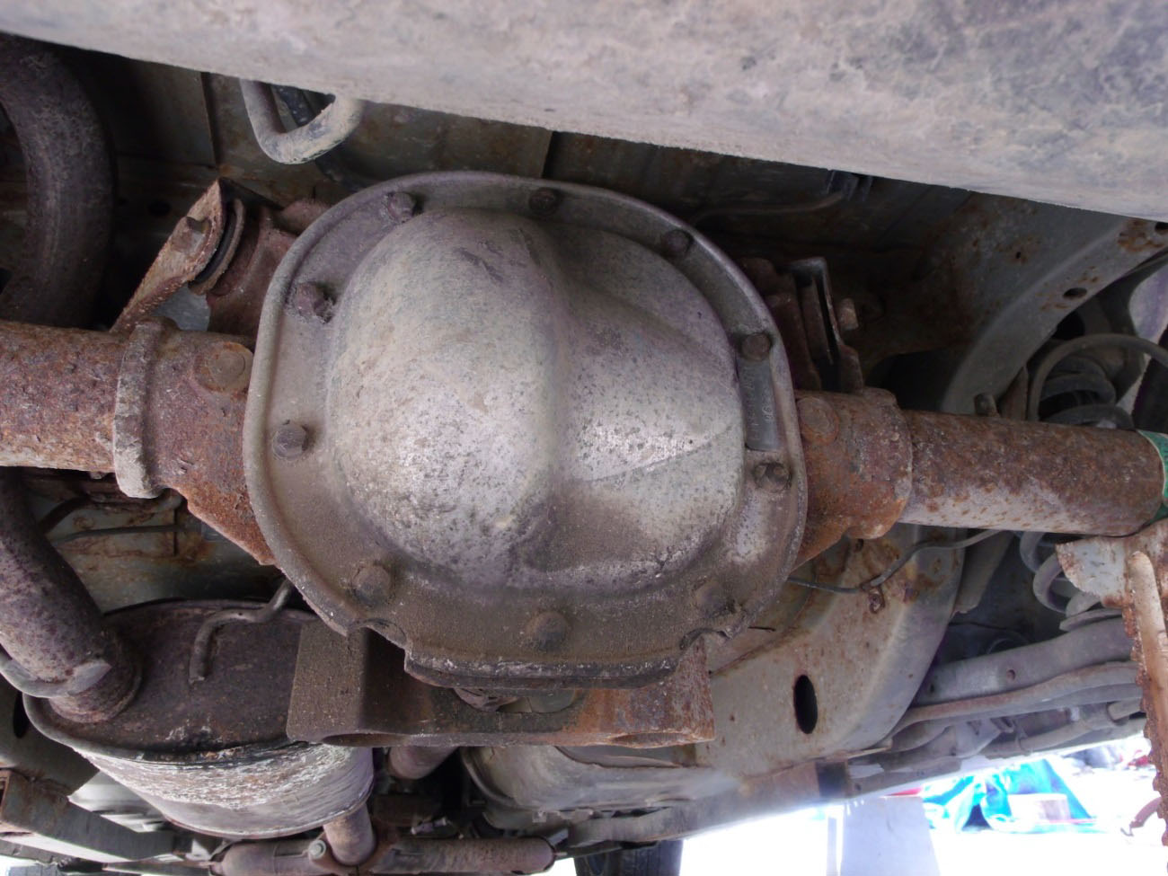
Fig. 1
4. Remove both rear wheels
5. Using adjustable pliers squeeze together the parking brake lever and remove the brake cable from the retainer (Fig. 2) and the “C” ring from the cable (Fig. 3).

Fig. 2
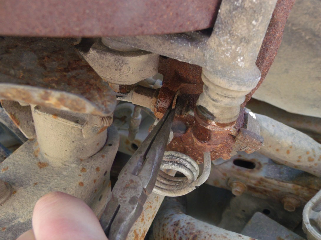
Fig. 3
6. If you are planning to replace brake pads, then the two caliper retaining pins should now be removed. Otherwise, the two caliper support bracket bolts should be removed (Fig. 4) and carefully suspended out of the way so as to not stress the flexible brake hose. (Fig.5)
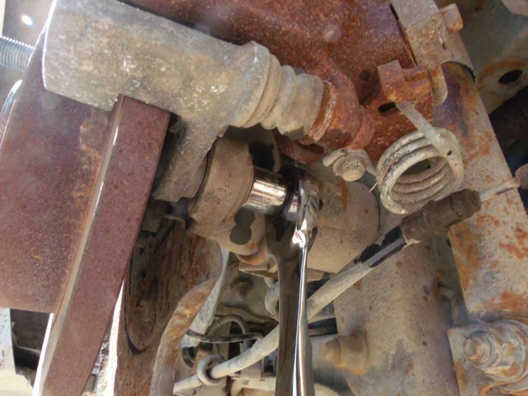
Fig. 4
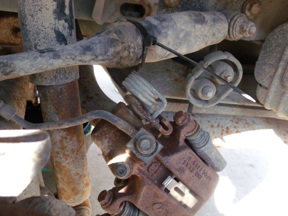
Fig. 5
7. Remove the brake rotor from the axle studs and the abs sensor magnetic pickup from the brake adapter flange (Fig. 6). Damage may occur to the abs sensor during removal. If any noticeable damage does occur one should replace the sensor.
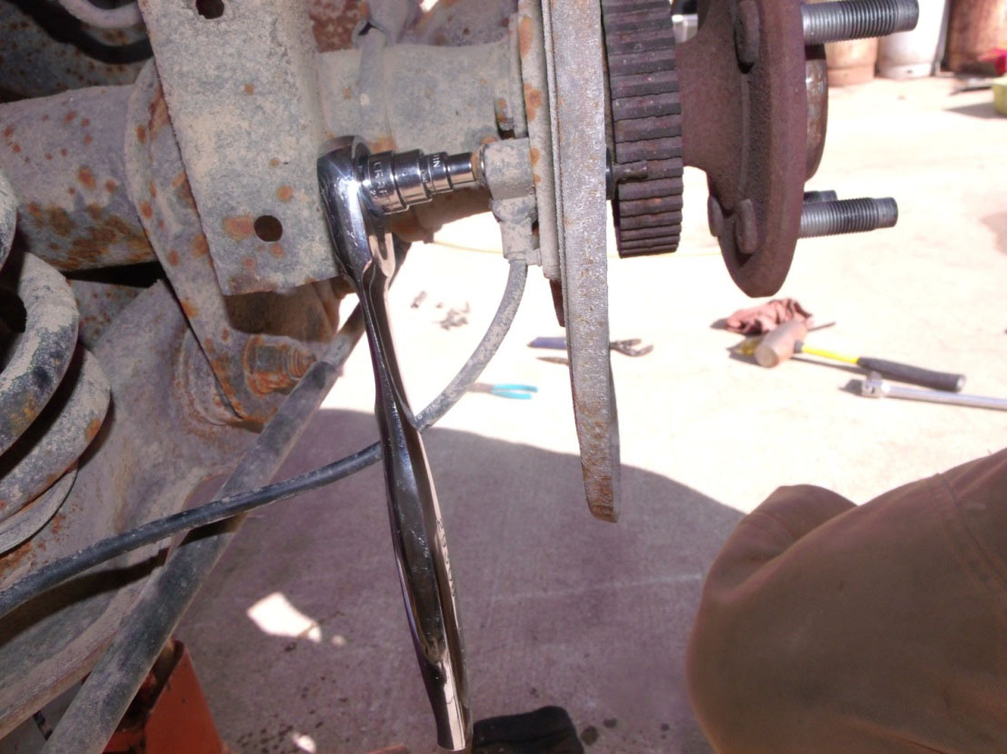
Fig. 6
8. Remove the differential pinion shaft lock pin (Fig.7). Then push the pinion shaft in an inch then rotate the differential 180 degrees and pull the shaft out (Fig. 8).
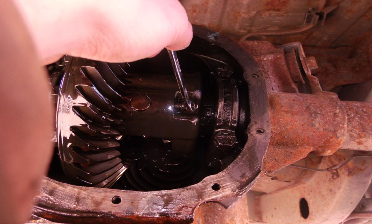
Fig. 7
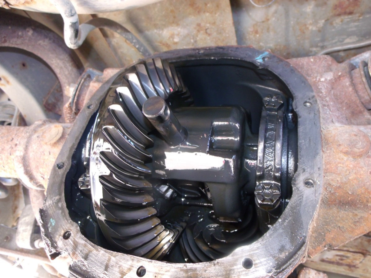
Fig. 8
9. Rotate the differential to expose the retaining U washers. Push both axle shafts in toward the center of the differential allowing the removal of the washers (Fig. 9).
Warning: Be careful when rotating differential case without having the pinion shaft installed. Excessive force could cause the spider gears to rotate out of the case.
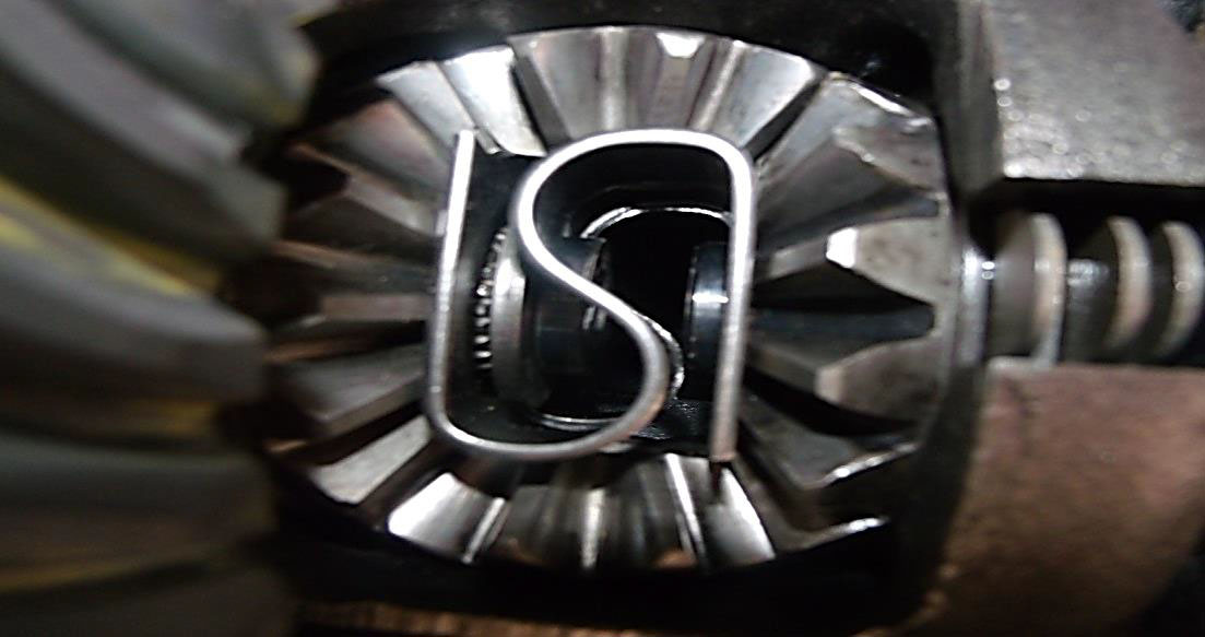
Fig. 9
10. Carefully remove each axle. Mark for reassembly.
11. Using a chisel or flat-head screwdriver tap all the way around the seal to slowly collapse it. Note that the original axle seals are folded over the axle end. Carefully chisel the seal to unfold it.
12. Tap until you can remove the seal. (Fig. 10)
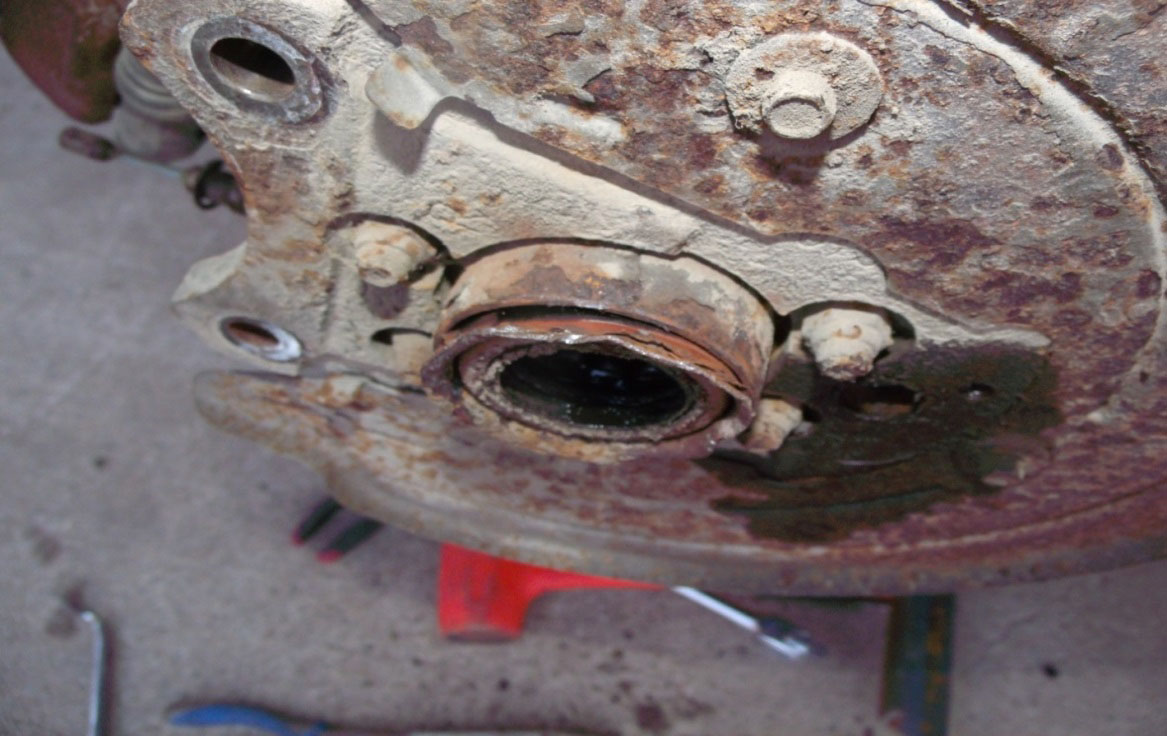
Fig. 10
13. Remove any debris that may be in front of old bearing. (Fig. 11)
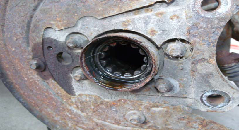
Fig. 11
14. Using either a slide hammer (Fig. 12) or p jaws (Fig. 13) remove the old bearing
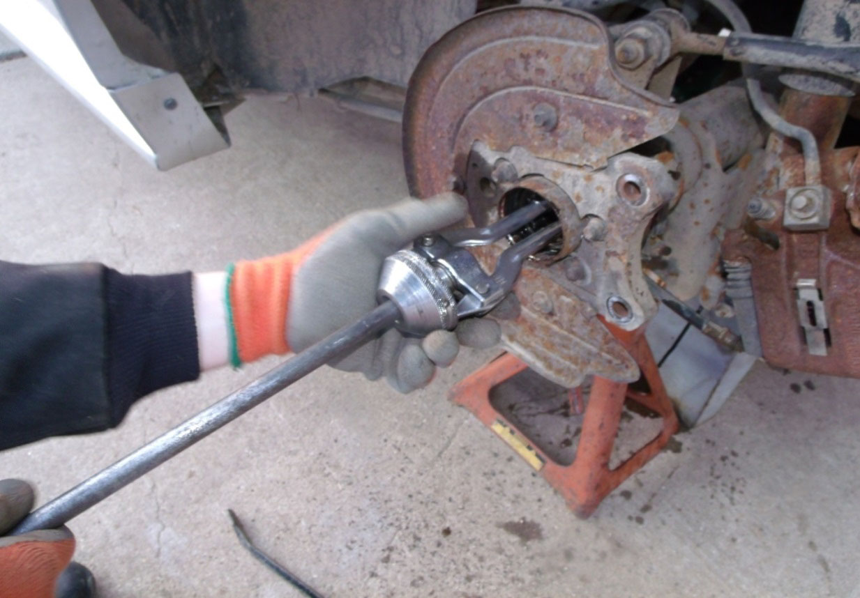
Fig. 12
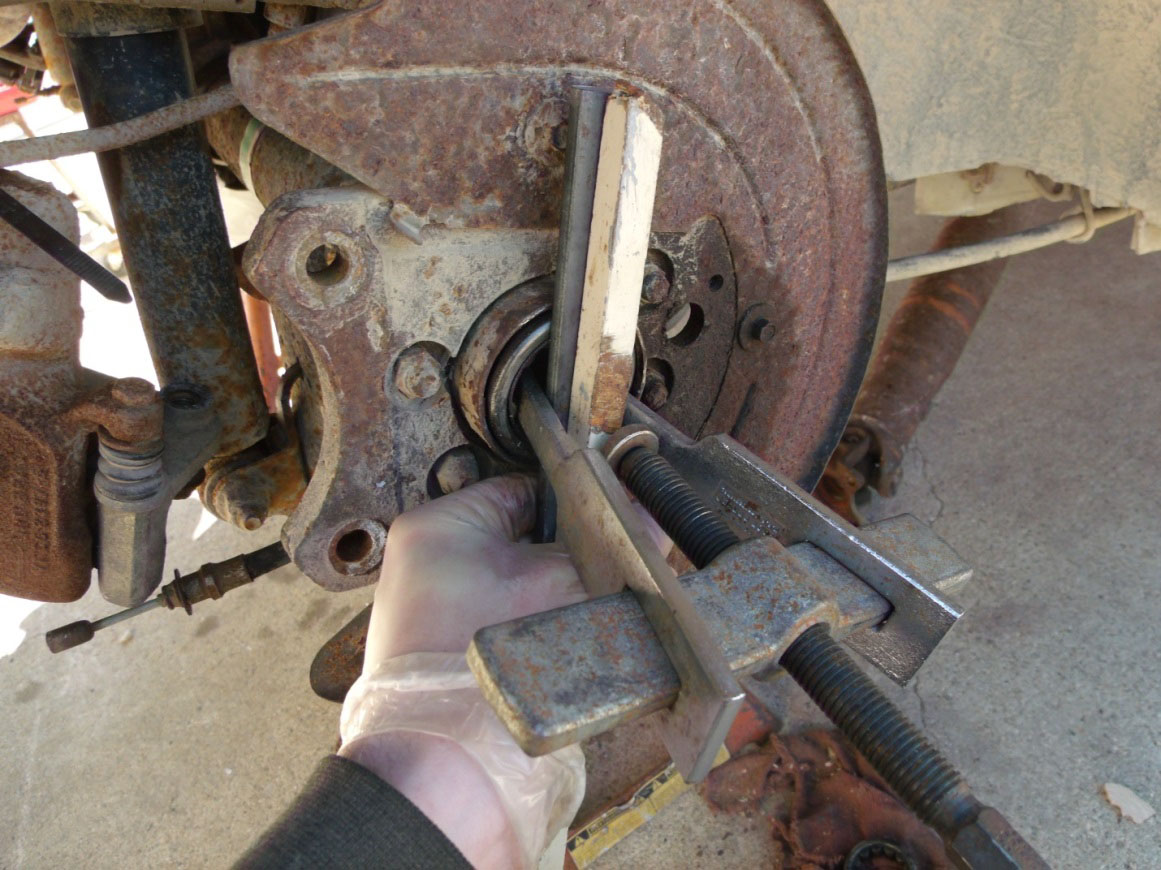
Fig. 13
15. Clean axle bore thoroughly to remove any debris and or old oil.
16. Lightly lubricate the axle bore with new gear oil to ease installation.
17. Using a bearing race installing tool or an appropriately sized socket tap the new bearing into the axle. (Fig. 14)
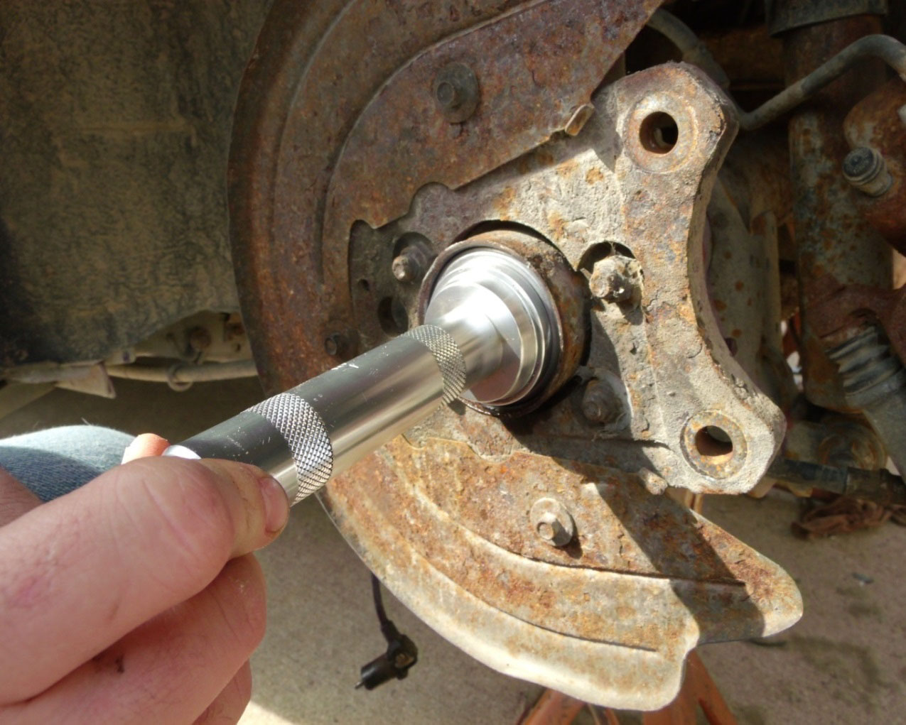
Fig. 14
18. Once the bearing is fully seated, thoroughly clean the oil from the axle where the seal will seat. This is done to ensure no leaks will occur from the outside of the seal.
19. Install the seal using a seal installing tool or an appropriately sized socket. (Fig. 15)
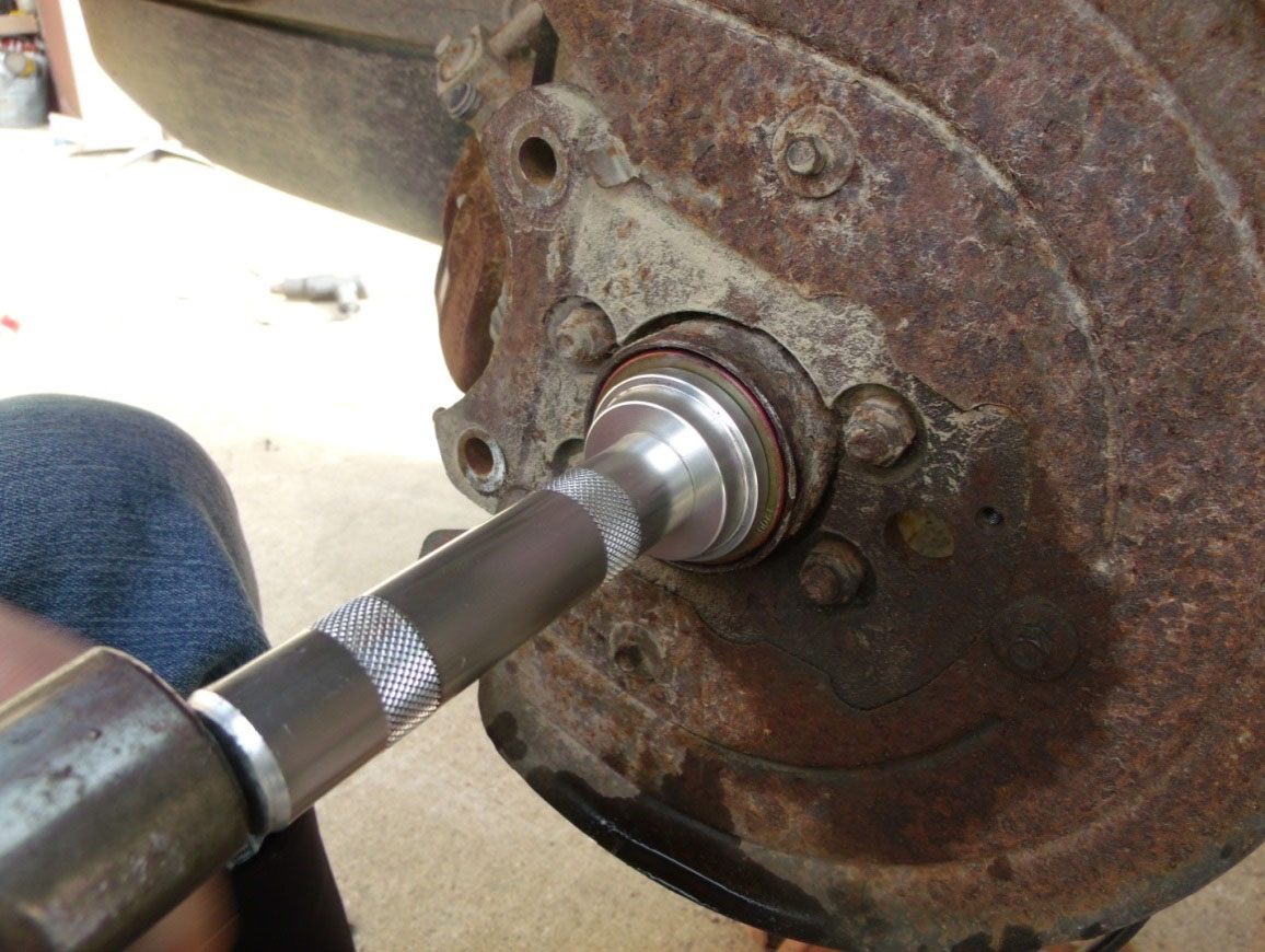
Fig. 15
20. Seal and bearing fully installed. (Fig. 16)
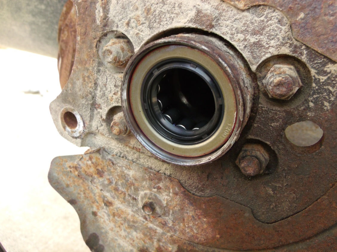
Fig. 16
21. Lubricate the seal rubber and the bearing with new gear oil to prevent damage during axle installation and to prevent the bearing from running dry during start up.
22. Clean the axle shafts then carefully reinstall them back into the axle side from which they were removed.
23. Insert the U washers into the axle ends without damaging the retaining O-ring. Then pull back on the axles until they lock into place. (Fig. 17) Warning: Be careful when rotating differential case without having the pinion shaft installed. Excessive force could cause the spider gears to rotate out of the case.
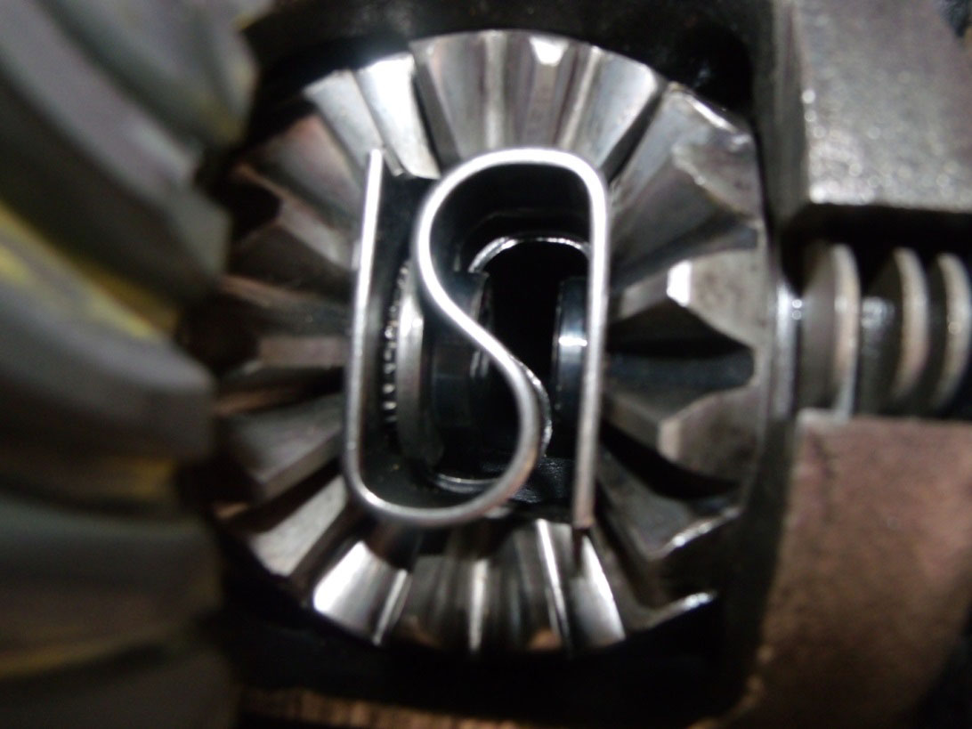
Fig. 17
24. Insert the differential pinion shaft with proper orientation until flush with case.
25. Install the differential pinion shaft lock bolt with a drop of red Loctite thread locker and tightened to 26 lb-ft. of torque. Preferably install a new lock bolt
26. Remove old gasket material from axle housing and housing cover. After making sure the mating surfaces of the cover are clean, dry and free of nicks and scratches, apply a 1/8” bead of Permatex gasket making material or equivalent around the entire cover and around each bolt hole. Apply a drop of blue Loctite thread locker to each bolt and tighten to 33 lb-ft of torque for steel covers and 24 lb-ft for aluminum covers. (Fig. 18)
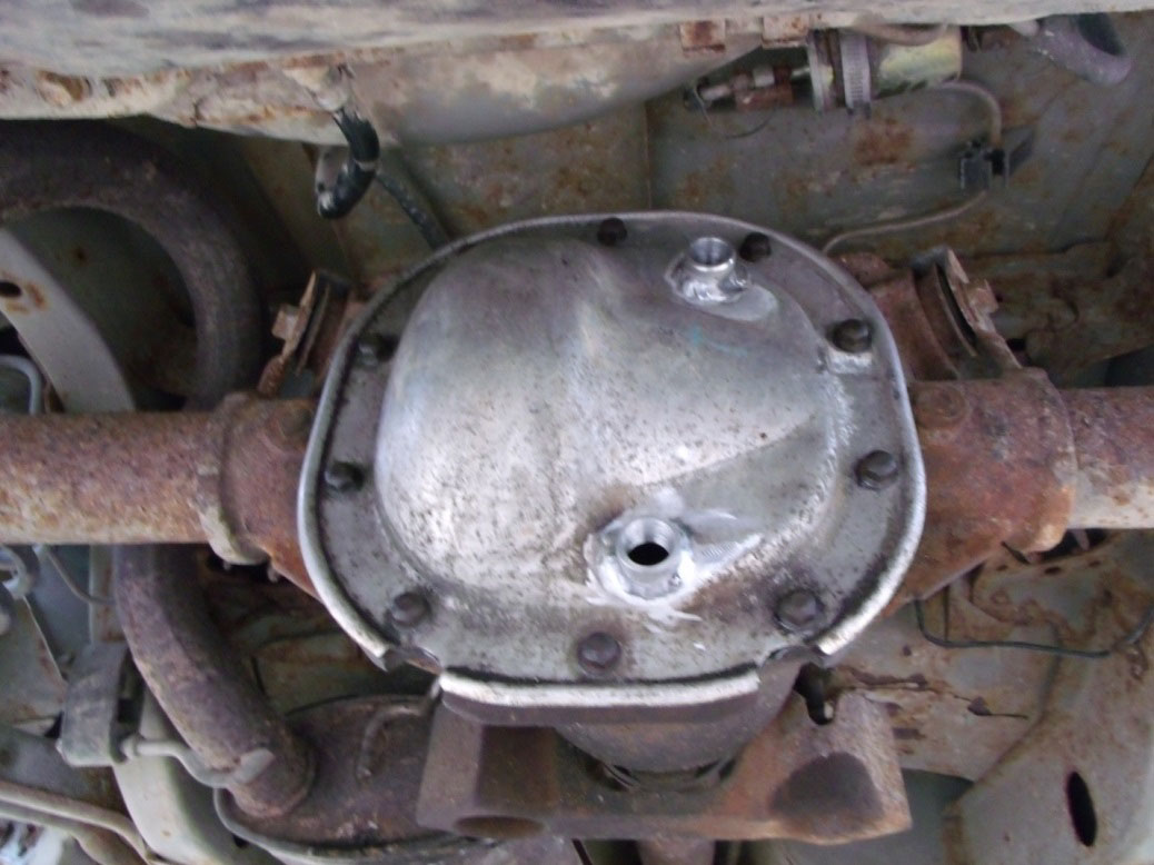
Fig. 18
27. If you have a Traction-Loc differential and are using a gear lube that doesn’t already contain a friction modifier, add 75W-90 weight premium gear lube to within ¼ to ½ inch of the bottom edge of the filler hole. Then
28. Add a 4 ounce bottle of Ford Additive Friction Modifier. Otherwise, fill just to the bottom edge of the filler hole and torque the plug to 22 lbs-ft.
29. Clean the magnetic probe of the antilock sensor pickup and install into brake adapter flange by applying a drop of blue Loctite thread locker to the bolt and torque to 133 lbs-ft.
30. Slide the brake rotors on and attach the caliper support bracket with a couple drops of blue Loctite thread locker to each bolt and torque to 65-87 lbs-ft.
31. Insert the parking brake cable into the retaining hole and secure it by sliding the “C” ring into place.
32. Squeeze the parking brake lever together and insert the end of the cable into the retaining loop.
33. Remount the rear tires and torque to 85-104 lbs-ft.
34. Lower vehicle, reattach the negative cable to the battery and test drive. Check for any leaks.
Installation Instructions Written by AmericanMuscle Customer Ryan Loney 4/16/2014
