FREE 1 to 3-Day Delivery on Orders $149+ Details
How to Install J & M Adjustable Caster Camber Plates (11-14 All, Excluding GT500) on your Ford Mustang
Installation Time
4 hours
Tools Required
- ratchet
- 10mm, 13mm, 17mm, 18mm, 19mm, 21mm sockets
- 10mm & 21mm wrenches
- torque wrench
- jack
- jack stands
- spring compressor
- trim panel tool
Shop Parts in this Guide
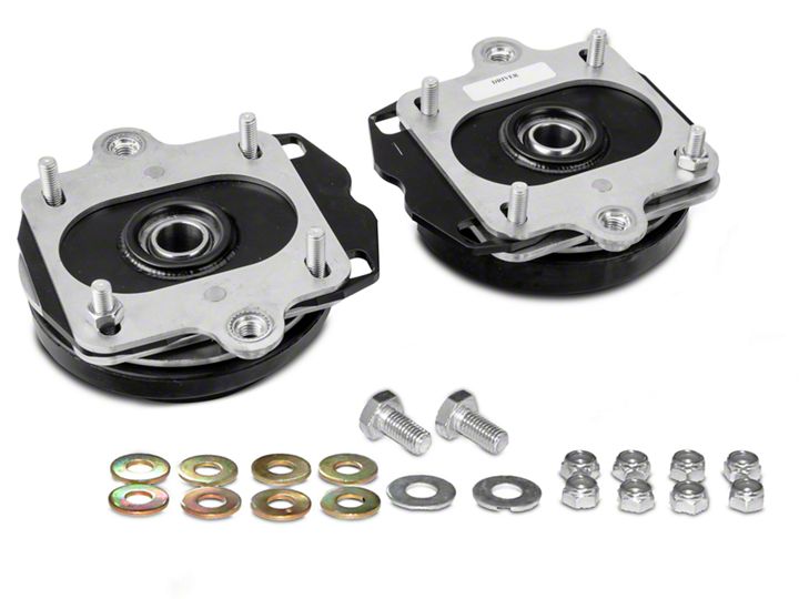
J&M Products once again outdoes our competitors with these fully adjustable PATENT PENDING Camber & Caster plate assemblies for the 2005-2010 and 2011-up Ford Mustangs. This Camber/Caster kit is the ONLY kit that comes complete READY to bolt in right out of the box (no need to swap anything over from the factory mount). Whether you are using the car for street, autocross, road racing or drag racing these plates are designed for you. These are the only plates that have an offset design allowing for you to install them in the street orientation or a race orientation allowing for the most camber adjustment available compared to any other plate on the market. Just like our other Camber/Caster plates these come with a full lifetime warranty to the original purchaser of the product.
Benefits:
• Allows for camber and caster adjustment not available from the factory
• Allows you to align your Mustang back to factory specifications even when lowered
• Camber & caster are adjustable separately.
• Offset design allows for either street use or race use alignments.
• Provides for caster adjustment not found on the factory mounts
• Caster adjustment to allow correction for OEM production tolerances.
• Alignment is easily adjusted at the top of the strut tower.
• Spherical bearing eliminates un-wanted deflection and precisely locates the strut shaft during cornering.
• Completely assembled and bolts in with no need for extra drilling or cutting.
• ONLY kit that includes everything needed to install all the way down to the rubber spring isolator.
• Unlike competitors you don’t need to remove parts from the factory mount and install on our mount.
Product Features:
• Over 2.5 degrees of camber adjustment, adjustable without affecting caster.
• 0.7 degrees of range of caster adjustment.
• PTFE lined spherical bearing manufactured in the USA.
• All parts are either plated or powder coated for great looks and long lasting protection.
• US Patent Pending.
• Lifetime warranty on the entire camber plate to the original owner.
Note: These Camber/Caster plates are side specific.
Camber/Caster Plate Installation Sheet:
1. Raise the vehicle to adequate working height and properly support the vehicle using proper jack stands (not a jack), then remove the wheels. If you have a strut tower brace, remove that as well. Re-install the nuts on the strut after you remove the brace. Remove the 10mm bolt that holds the brake line to the strut. Next, remove the wiring harness that is clipped to the strut. Use the trim panel tool to remove the wiring clip.
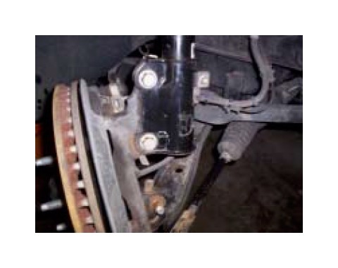
2. Remove the 18mm nut on the strut for the sway bar end link. Remove the end link from the strut by pushing it through the hole. Do Not Use Impact Gun
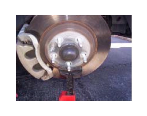
3. Support the rotor with a jack stand, jack, or and then remove the two 18mm bolts that attach the strut to the knuckle. After the nuts are removed, you may need to wiggle the strut back and forth to be able to slide the bolts out of the knuckle. Once the bolts are removed, you will see why a jack stand was needed to support the rotor and knuckle assembly. If not properly supported, damage to the brake lines, wiring, or ball joints could occur. If you prefer you can carefully remove the spindle to strut bolts and carefully remove them while support the rotor by hand. Once they are removed you will want to safety tie the spindle/rotor assembly to the anti-roll bar to make sure the brake line does not get damaged.
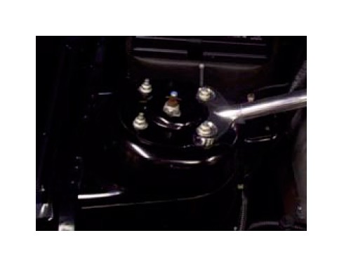
4. With everything under the car loosened, you can now remove the 4 nuts in the engine bay. Once these 4 nuts are removed, the strut will come right out, so be sure to hold the strut while removing the fasteners.
5. With the strut removed, you can now compress the spring with the spring compressor. Many auto parts stores have a tool rental program if you don’t have your own. Usually, you leave a deposit for the tool, and get 100% back when you return the tools to the store. Install one compressor on each side of the spring, and engage the safety pins. Next you can start to compress the spring, compressing both sides evenly. Take your time and do a little bit on each side until the spring is compressed.
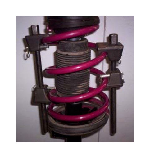
6. The spring is compressed enough when the spring has no pressure on the upper mounting plate, as shown to the right.
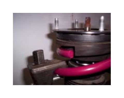
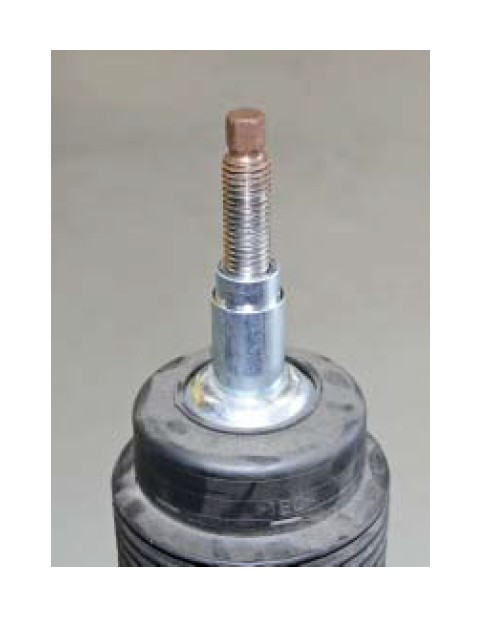
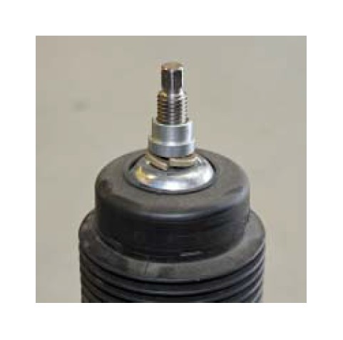
7. Once the spring is compressed, remove the 21mm nut on the top of the strut. You may need to hold the strut shaft with a 10 mm wrench to prevent it from spinning. Once the nut is removed, remove the upper strut mount. We do NOT recommend using impact guns on struts or shocks.
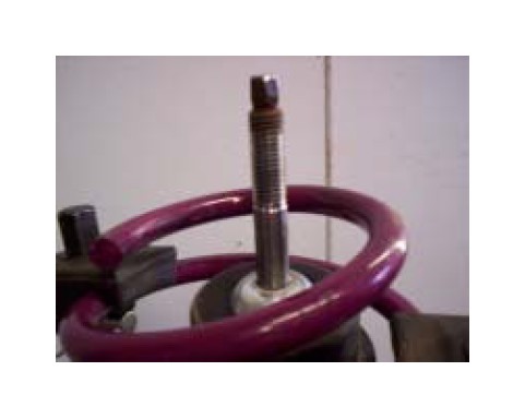
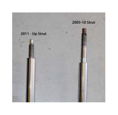
8. Figure out which strut you have using the image
below. If you have 2005-2010 proceed to step 9. If
you have 2011-up struts skip to step 13.
THESE CAMBER/CASTER PLATES ARE SIDE SPECIFIC!
9. 2005-2010 struts you will install the long 1.550” spacer as shown below over the strut shaft.
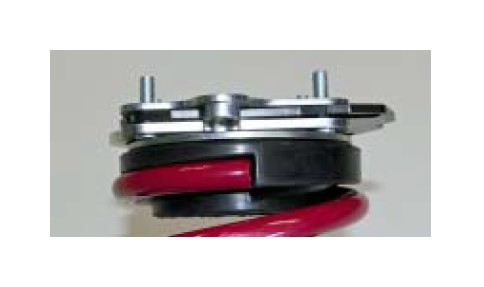
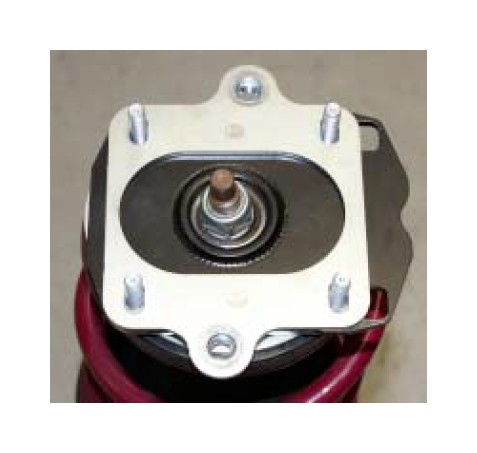
10. Place the camber plate over the strut shaft and make sure spring seats properly into the rubber spring isolator like shown. Strut not shown for clarity.
11. Place the small spacer that measures .465” total length over the strut shaft. Spring not shown.
12. Re-Install the strut nut and torque to factory specifications. Spring not shown. (Do Not Use Impact Guns). Proceed to Step 16
THESE CAMBER/CASTER PLATES ARE SIDE SPECIFIC!
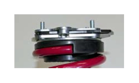
13. 2011-Up struts install the dust cover, grade 8 lock washer, and the .600” long reducer spacer with the small diameter facing upward as shown.
14. Place the camber plate over the strut shaft and make sure spring seats properly into the rubber spring isolator like shown. Strut not shown for clarity.
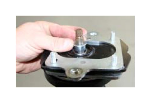
15. 2011-Up will use the supplied machined reducer strut nuts as shown. Please note we supply two different sets of nuts. The silver color is course thread and the yellow zinc ones are the fine thread. Some aftermarket struts use a fine thread compared to the factory nut. Please make sure to test fit which nut on the strut by hand before torquing to avoid damaging the threads. Once you have determined the proper reducer nuts torque the strut nut to factory recommended torque specifications. Do Not Use Impact Guns. Spring not shown.
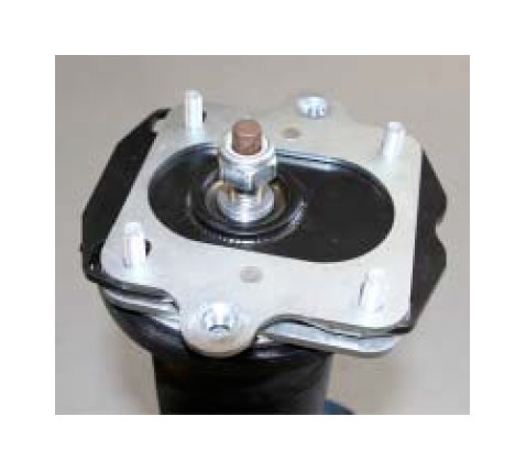
16. Once the strut nuts have been torqued you can now remove the spring compressor. Carefully remove it and make sure the springs are seated properly in the indexed area of the strut and camber plate spring seats.
17. The bottom of the strut tower must be smooth and free from any raised metal or flash. Run you finger across the underside of the tower and make sure it is smooth and free from scratches. If it is not smooth file or sand down any rough spots.
18. The camber plate has a offset bearing design which allows you to install them in a street setting or a race setting. To install in the street setting which will allow you to more positive camber for lowered cars simply install with the notch toward the inside of the car (engine side) and the race setting you will install the notch toward the fender (outside) of the car.
STREET RECOMMENDATIONS:
If you are looking for a factory alignment setting and you are 1” or more lowered we recommend using the street setting/orientation.
If you are looking for a factory alignment setting and you are 1” or less lowered we recommend using the race setting/orientation.
ROAD RACE RECOMMENDATIONS:
Depending on the type of racing you are doing will determine how much camber you want. Typically road racing and auto cross will need more negative camber. If you are setting your car up for this we recommend using the race orientation.
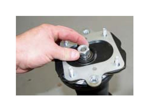
19. We install one 8mm nut onto one of the studs to keep the caster plate in place during shipping. Make sure to remove this nut before trying to install the assembly into the car.
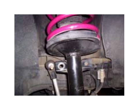
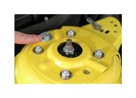
20. Carefully reinstall the strut assembly into the vehicle using the desired orientation from step # 18 and install the supplied 8mm washers and 8mm locking nuts. Do not tighten.
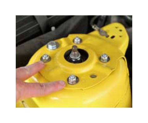
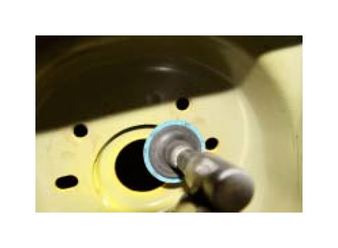
21. Install the supplied M10 x 20mm bolt with 10MM support washer into the caster slot in the factory tower. You can now snug all 5 mounting bolts and nuts.
22. Reattach the spindle to the strut and torque the bolts to the factory setting of 148 lb-ft. Note: Ford recommends replacing these bolts every time you remove them. You can purchase these from your local Ford dealer.
23. Reattach the ABS sensor wire and brake line bracket and torque to Ford specifications of 15 lb-ft.
24. Reattach the sway bar end link and torque to factory specifications of 85 lb-ft. Do not use an impact gun.
25. With the tires still off the ground slide the strut all the way forward toward the front of the car. You can now tighten the M10 bolt to 26 lb/ft.
26. We recommend centering your strut shaft in the center of the strut tower opening to get you to the alignment shop. Once you have centered the strut you can torque the 8mm locking nuts to 20 lb-ft.
27. Repeat the steps for the other side.
28. Install the wheels and safely lower the vehicle off the jack stands to the ground. Make sure you torque your wheels to the factory torque specifications.
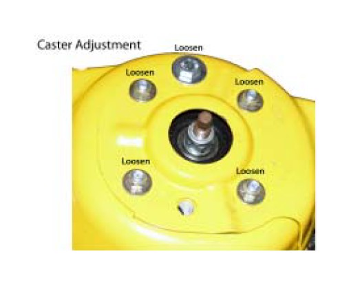
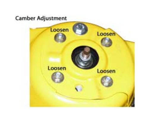
29. Align your vehicle to your desired alignment specifications or factory specifications if you are happy with them. Caster should be set first.
Alignment Notes:
You will not be able to adjust these plates with the vehicle on the ground or the suspension loaded. The front must be raised in order to adjust the camber/ caster plate. Due to the anti-roll bar loading it may be required to lift both front tires off the ground to make adjustments.
These J&M camber/caster plates have separate adjustments for camber and caster. You must adjust caster first and lock down the M10 caster bolt to 26 lb-ft and then adjust camber.