 FREE 1 to 3-Day Delivery on Orders $149+ Details
How to Install KW Suspension V3 Coilover Kit (05-14 GT, V6) on your Ford Mustang

Shop Parts in this Guide
INSTALLATION INSTRUCTIONS
Before you begin installation , please read the following carefully:
- Ensure that the TUEV certificate matches the vehicle specifications (front vehicle identification number (VIN)) etc...
- The suspension components must match the suspensions application specifications (springs and shock/struts identification numbers).
- The instructions have to be strictly observed.
KW Coilovers for automobile suspensions are designed for easy installation. If not otherwise stipulated in these instructions, all suspension components are installed and removed in accordance with the manufacturer's specifications for installing and removing standard springs and damper components. At the time of printing all instructions and specifications are correct. However please check with your local KW dealer or the KW website www.kwsuspensions.com (US-program only) www.kwautomotive.de (European program) for the latest updates.
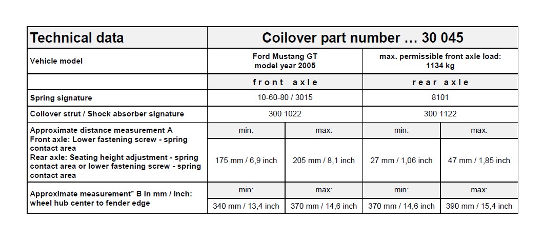
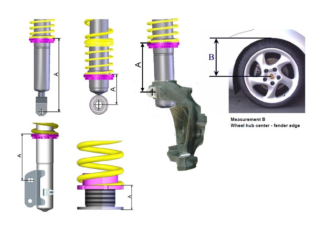
Calculating the adjustment range (distance measurement A) : (Photos are examples only)
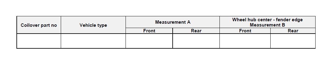
Please enter the adjusted height of the modified car into the list:
* IMPORTANT: The allowable measurement between wheel hub center and fender edge as indicated above, may not exceed this measurement when using standard fenders.
Danger:
1. Always follow the latest accident prevention regulations (not applicable for North America) for each step to prevent any serious bodily harm or injury.
2. We recommend the use of a vehicle hoist or lift when installing the suspension. If a lift is not available and jacking equipment is used, make sure that the vehicle is secured with commercial wheel blocks and jack stand to ensure safety.
3. The suspension components may only be installed by trained technical personnel using the proper tools.
4. The General Installation instructions, as well as the Technical Inspectorate (German TUV) documents must be read BEFORE attempting installation.
5. Never use impact wrenches or guns to install or remove shock absorber piston hardware.
6. Never disassemble or cut open shock absorbers and/or shock absorber inserts. They contain oil under pressure. Danger of explosion.
7. Before driving on public highways, carry out the work steps on page 7, items 11 through 14 after installation.
8. The suspension regulation (when available) needs to be disabled through an authorized dealer.
9. Please take care in any case that fittings (for example fittings of shock absorber housings or fittings of the lower control arm in the housing of the wheel bearing) are free of dust and oil. (see manufacturer guideline)
General Instructions for Use:
1. When adjusting the vehicle height, make sure that the threads are clean and free of debris. After initial cleaning, move the perch by 10 mm (0.4 Inches) downwards, and then clean the area that you desire to adjust the perch (up or down).
2. During height adjustments on separate shock and spring systems, remove the perch from the vehicle to adjust the height.
3. After adjusting the vehicle height, repeat steps 11 through 14 from page 7.
4. In the area of the piston rod and the sealing package of the new and used damper might be oil and grease collected. This could either be caused by using a special black grease during assembling the washer or due to accumulation of streak oil. Further more oil is used during assembling the cartridge and rod guide. There is no reason of worrying about and damage, as in this area also dust and dirt used to be collected.
General Mounting Specifications:
1. We recommend the use of a vehicle hoist or lift when installing the suspension.
2. Caution: If the vehicle is equipped with ride height sensors, they should be removed before removal of struts or dampers, otherwise damage may occur.
3. The struts should be removed as specified by manufacturer's instructions.
4. Manufacturer recommended tools for removal of the original struts, or a suitable spring compressor, must be used in order to remove most factory mounted suspension systems. 5. Mount the complete suspension system as described on the following pages.
6. Never use impact drivers to install nuts on the piston rods as permanent damage may occur. It is imperative that you do not damage the piston rod surface, through use of pliers etc, as the smallest damage will result in seal damage, and will not be covered under warranty.
7. Stay within the lowering range specified in the table on page 3. Example: With a specified range of 20 - 60 mm (0.8 - 2.3 Inches), 40 mm (1.5 Inches) is your height adjustment range.
8. Ensure that the set screw on each spring collar is tightened to prevent movement of the spring perch. On vehicles with separate shock/spring combinations, no set screw is necessary. Caution: Do not over tighten the set screw. Maximum torque is 1 - 2 Nm (0.74-1.47 ft-lb).
9. Install the suspension components in the vehicle as specified by the vehicle manufacturers in their document.
10. Except as noted, all torque values must comply with manufacturer recommended specifications.
11. After assembly and installation is complete, the vehicle should be rolled onto level ground. Once on level ground, measure the vehicle height and adjust to the customer's requirements, within the prescribed lowering range. Caution: Wheel hub center-wheel arch maximum measurement in the table of page 3 must not be exceeded! Also take into account minimum road clearances specified in the table on page 7 (only valid for Germany!). Caution: It is common for the vehicle suspensions to settle by an additional 5 - 10 mm (0.2 - 0.4 Inches)
12. Examine the clearance between the tires and the suspension over the full range of motion of the wheel. The minimum clearance between the suspension and the tire is 4 mm (0.16 Inches). If this clearance is less than 5 mm (0.2 Inches), wheel spacers may be necessary. With strut designs that are located close to the wheel, but that have no steering functions, use 100 mm (3.9 Inches) spacers on diagonally opposed wheel (e.g. front right, rear left). In this position, you must be able to achieve the minimum clearance required. You can also check the clearance between tire and body. Caution: With torsion beam trailing arm axles, this method is not sufficient. The wheel must be under full load as well as test driven to properly calculate the clearances of 5 mm (0.2 Inches) from any other components.
13. The geometry of the suspension needs to be adjusted according the regulations of the vehicle manufacturer. If a value cannot be reached due to the difference in the height, a optimal value next to the tolerance range of the vehicle manufacturer needs to be adjusted.
14. All components that are controlled by vehicle ride height (e.g. headlights, brake bias regulator etc.) must be adjusted as specified by the vehicle manufacturer instructions and procedures.
15. For vehicles with ESP, DSC or EPC your new suspension components may cause an engine fault code to appear. This is only temporary as the vehicle electronics adjust to the new components/height. On some models this will end after driving approximately 3-5 miles, or through turning the steering wheel from full left to full right. On other models, this must be reset through the factory diagnostic port by a qualified technician.
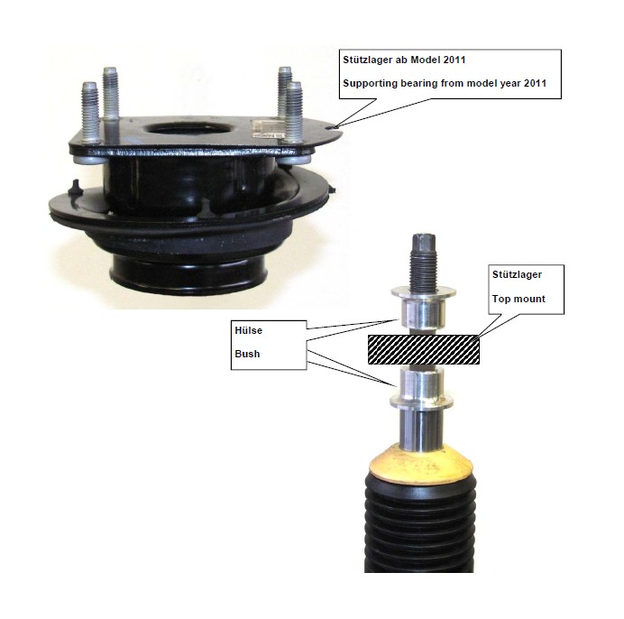
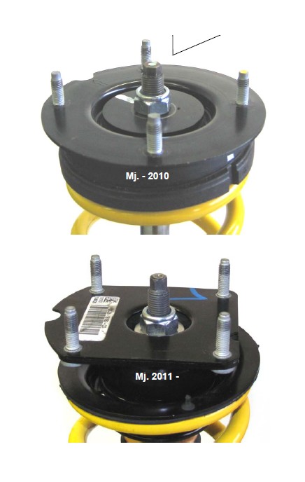
The VA top mount changed from model year 2011. Assemble necessarily the supplied bush below and above the top mount as shown on the picture. In model up to year 2010 will be the supplied bush not required!
Supporting bearing from model year 2011
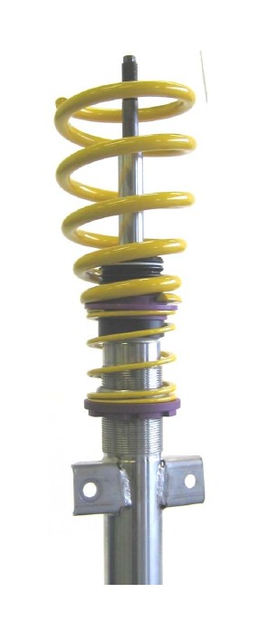
Supplied coilover strut.
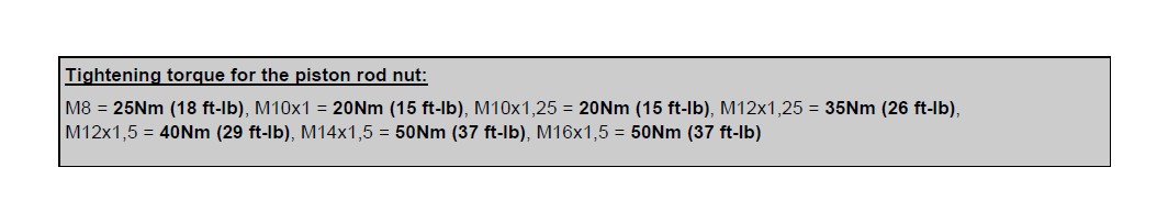
Insert the original top mount and fix it with the supplied stop nut. Tightening torque for the piston rod nut is 50 Nm (36 ft-lb). Please install the strut unit to manufacturers recommended settings regarding tightening torque and fixing specifications.
After you have completed installation of the suspension, check the clearance of the wheels/tires to the front suspension strut. The minimum clearance at the narrowest point may not be less than 5 mm (0.2 Inches). If the wheel/tire does not meet this minimum measurement, TUEV approved wheel spacers may be necessary.
Rear axle:
Press in the supplied bump stop into the axle as shown on the picture
Mount the rear axle height adjustment perch between spring and axle, remove the original spring supporting disc. Remove the height adjustment perch to correct.
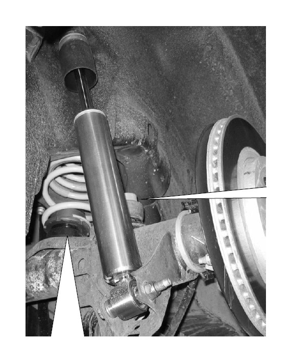
Unless there is no bump stop supplied by KW the factory bump stop has to be used. The factory bump stop has to be in a good condition, otherwise it has to be replaced.
Tightening torque for the piston rod nut is 25 Nm (18 ft-lb). Please install the damper unit to manufacturers recommended settings regarding tightening torque and fixing specifications.
