FREE 1 to 3-Day Delivery on Orders $149+ Details
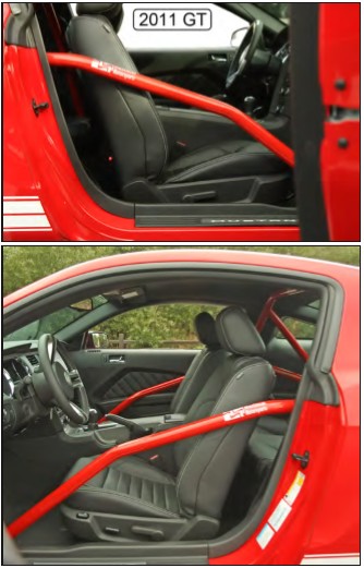
How to Install Maximum Motorsports 6-Point Drag Race Roll Bar (05-14 Coupe) on your Ford Mustang
Installation Time
2 hours
Tools Required
- T-47 Torx Bit
- Standard assortment of hand tools
- 8mm socket or wrench
- 10mm deep socket
- 13mm wrench and socket
- 15mm wrench and socket
- 9/16" wrench and socket
- 3/4” socket
- Torque wrench
- Drill
- 7/16" drill bit (more than one may be useful)
- Floor jack and 4 jack stands
- Straight-edge or long ruler
- Hacksaw or Wood Saw
- Center punch
- 1/8" pilot drill
- 1-3/4" Hole saw
- 2" Hole saw

Shop Parts in this Guide
Read all instructions before beginning work. Following instructions in the proper sequence will ensure the best and easiest installation.
The latest version, high-quality COLOR instructions are available online at www.maximummotorsports.com. Check the bottom of your installation instructions for the date and compare it to the copy available online.
Do you want to die? If not, pay attention to this:
The rear braces must be welded to the main hoop. That step is not optional. The rear spuds are not structural; they are there only to align the rear braces to the main hoop for easy welding. If the rear braces are not welded to the hoop and the car rolls over, you will probably be killed because the spuds will break off the hoop and allow the roll bar to collapse. Follow the instructions and properly weld the rear braces to the main hoop. Check the MM Facebook page and website for a graphic example of how good the MM roll bars are when properly installed.
With MM’s innovative design, the rear braces bolt to the main hoop, which holds them in the correct position so they can be welded while outside of the car. This unique design reduces shipping charges, and saves you the time and effort of stripping the interior of your car to protect it from welding sparks.
NOTE: Due to the required welding for installation, the MM roll bars are shipped uncoated. For best results, complete the installation, then remove the roll bar for either painting or powdercoating, and then reinstall. That way you will avoid wear and tear on your finish while drilling holes.
Preparation
• The vehicle must be safely supported on jack stands and have the rear wheels removed. For roll bars with the door bar option, the entire vehicle must be supported on jack stands to gain access to the plastic panel covering the fuel filter.
• The MM support brackets are shipped unpainted. We recommend painting the brackets prior to the actual installation so they don’t have to be removed once correctly positioned.
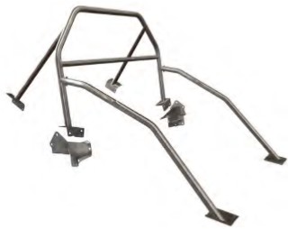
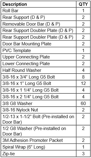
• Unpack the roll bar and remove the supplied hardware and mounting plates/brackets. Verify that the items in the hardware list below are present.
This kit contains:
Interior Removal/Preparation
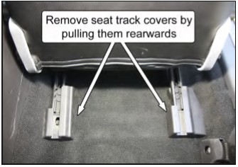
1. If currently installed, remove the front seats. Slide the seats forward to remove the two seat track covers.
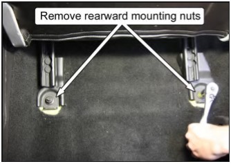
2. Next, remove the two rear hex nuts using a 15mm socket.
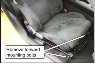
3. Slide the seats all the way back to remove the two front hex bolts using a 13mm socket.
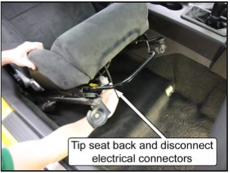
4. Tip the seat back to disconnect the wiring harness connectors for the air bag module and seat. Carefully pull the seats out of the car and place aside.
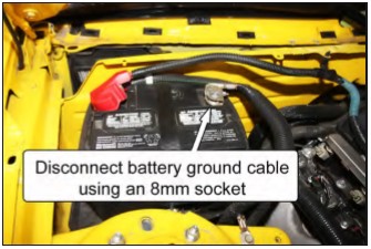
5. Disconnect the battery ground cable by using an 8mm socket.
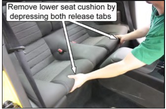
6. Remove the rear seat cushion. Push rearward on the two seat cushion release tabs while lifting up at the front to remove the rear cushion assembly.
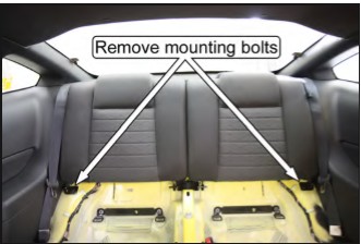
7. Remove the rear seat backrests. Using a 13mm socket, unscrew the hex bolt on the lower, outboard corner of each backrest.
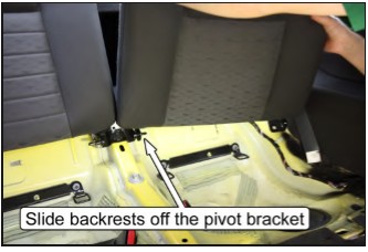
8. Pull the release strap to pivot the backrests down and slide the backrests off the center pivot bracket to remove them from the car.
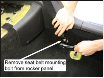
9. Remove the T-47 Torx bolts holding the safety belts to the rocker panels.
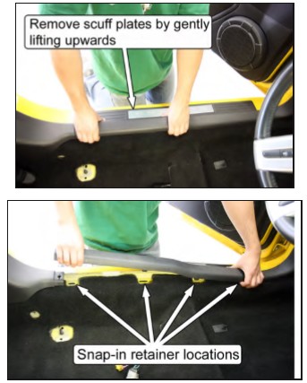
10. Remove the door scuff plates. Pull up at the ends and middle of the plates to disengage the three snap-in retainers.
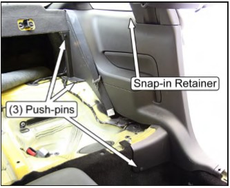
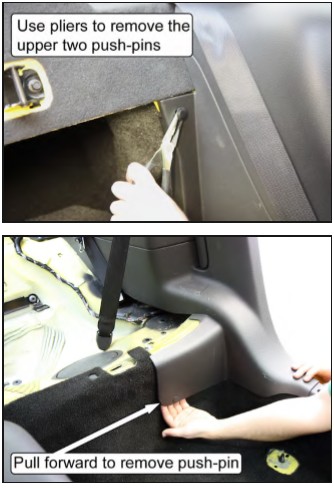
11. Remove the rear quarter panels. There are three push-pin retainers on each panel; one is located at the front of the seat bulkhead and two are at the rear seat backrest. Carefully pull the rear half of the panels inward to disengage the snap-in retainers located below the quarter window, and then pull the panels forward.
NOTE: Take care to avoid tearing the sound-deadening mat located beneath the panels.
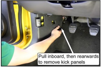
12. Remove both front plastic kick panels. Pull the portion closest to the firewall inboard to disengage the push-pin retainer, and then pull the panels rearward.
NOTE: The passenger-side panel may have an alarm switch connected to it. Be sure to remove the switch before pulling the panel out of the vehicle.
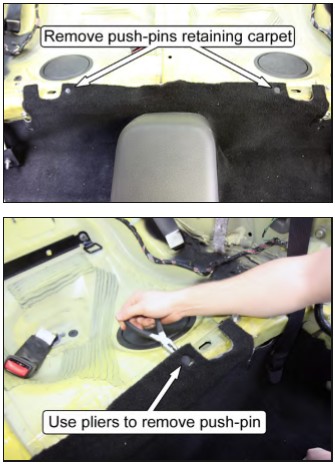
13. Remove the two push-pins retaining the carpet to the rear seat bulkhead.
14. Pull the driver and passenger sides of the carpet up and fold them over the center console to protect it during the remaining installation. Use the provided zip-tie to hold the halves together.
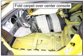
NOTE: If present, disconnect the wiring harness connected to the seat belt so that the carpet can be folded over the center console.
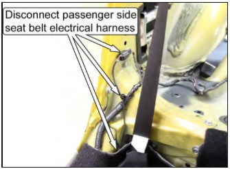
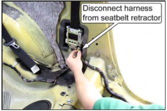
15. Relocate the wiring harness in the area adjacent to each B-pillar. Unfasten the harness retaining clips and pull the harness inboard to clear the factory support brackets. If necessary, get more slack by disconnecting the harness where it plugs into each of the seat belt retractors.
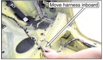
NOTE: There is a release clip that must be disengaged on the inboard face of the seatbelt retractor electrical connector on some vehicles. Use a small screwdriver to pop the release clip up, away from the connector.
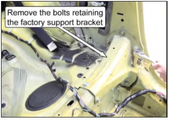
16. Unbolt and remove the two factory support brackets that connect the B-pillar to the rear seat bulkhead. Each bracket has seven 13mm hex head-sized bolts and two 15mm hex head-sized bolts.
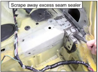
17. Scrape away any excess seam sealer around the factory support bracket mounting area.
MM Support Bracket Installation
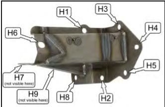
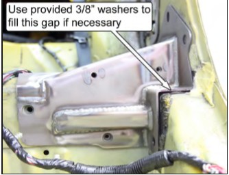
There will be gaps due to vehicle production tolerances between the MM support bracket and the vehicle. These gaps must be minimized to 1/8” or less around the B-pillar mounting holes. Extra washers are provided for this. Use the following steps to correctly position the driver- and passenger-side brackets. This picture identifies the individual holes:
18. Starting on the driver side, set the MM support bracket into position. The bracket should be resting against the B-pillar and the front of the rear seat bulkhead.
19. Check the gap between the bracket and the vehicle at Hole 2 (H2). Use the provided 3/8” G8 washers to close the gap to 1/8” or less. Then insert one of the factory mounting bolts into the hole to prevent the washers from dislodging.
NOTE: Small gaps are acceptable, as the vehicle and the MM support bracket will conform to each other as the mounting bolts are tightened.
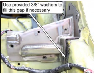
20. Check the gap between the bracket and the vehicle at H8. Use the provided 3/8” G8 washers to close the gap to 1/8” or less. When satisfied, insert one of the factory mounting bolts into the hole to prevent the washers from dislodging.
NOTE: It may be helpful to tape the washers to the end of a small screwdriver to aid in sliding them into position.
21. Install the remaining mounting bolts into the support bracket and tighten them by hand. Take note that H6 and H7 use the larger, 15mm hex head bolts.
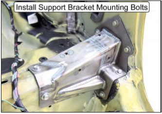
22. Using a wrench, tighten (but do not torque) all bolts in numerical order from H1 to H9 so the bracket can be properly seated against the vehicle.
23. Following the same numerical order, torque the 13mm hex-size bolts to 17lb-ft (23Nm) and the 15mm hex-size bolts to 48lb-ft (65Nm).
24. Repeat Steps 18-23 for the passenger-side bracket.
Main Hoop Installation
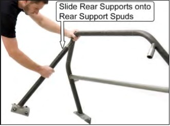
25. Slide the driver- and passenger-side rear supports onto the rear support spuds and secure them with the provided 3/8” x 2 ¼”-long bolts and 3/8” Nylock nuts. Only hand tighten: do NOT torque them yet.
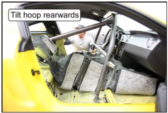
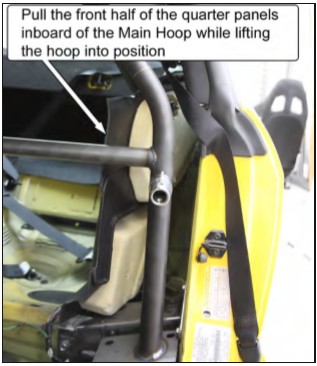
26. Place the roll bar into the vehicle by tilting the hoop forward and passing it through the passenger-side door. Once the roll bar is in the vehicle, tilt it rearward and place it onto the MM support brackets and the rear support mounting pads on the inner corner of each rear wheel well.
NOTE: Make sure that the hoop is as far forward in the vehicle as possible when tilting in rearwards into position. By keeping the hoop forward, it will allow the rear support pads to clear the plastic trim panels on the upper half of the B-pillars.
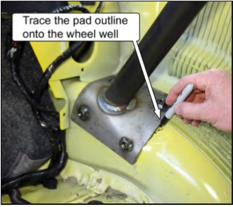
27. Trace an outline of the rear support mounting pads onto the driver- and passenger-side wheel well, and then remove the roll bar from the vehicle.
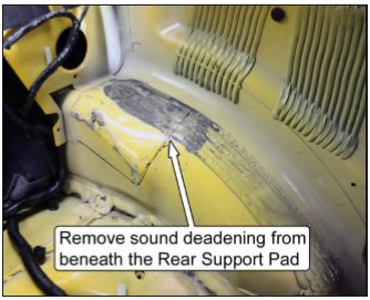
28. Remove the sound-deadening material within the outline using a chisel or other scraping device. Once done, reinstall the roll bar into the vehicle.
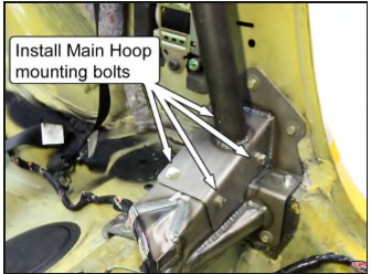
29. Loosely secure the hoop to the MM support brackets using the provided 3/8” G8 washers and 3/8”-16 x 1” G5 bolts.
NOTE: In some cases, it may be necessary to enlarge the holes in the main hoop mounting pads to provide clearance for the mounting bolts.
30. Slide the door bars onto the door bar spuds on the main hoop. Use two of the provided 3/8”16 x 2 ¼”-long bolts and 3/8”-16 Nylock nuts to loosely secure the bars in place. The door bar mounting pads should touch the rocker panel and rest flat on the raised bosses on the floor. NO
TE: If there is excess sound-deadening material beneath the door bar mounting pad, it will not rest flat against the floor pan. Use a chisel or other scraping device to remove the excess material as needed.
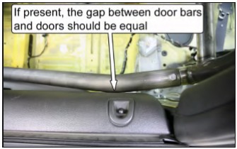
31. Center the roll bar in the vehicle by closing the doors and checking to see if both door bars are touching the door panel near the door bar spuds. If they are both touching, the roll bar is centered. the gaps between each door bar and each door panel are equal on each side of the car.
NOTE: Make sure to double-check that the door bar mounting pads are touching the rocker panel and resting flat on the floor once the doors are closed.
32. Temporarily tighten the bolts that secure the hoop to the MM support brackets.
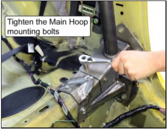
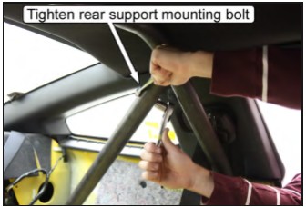
33. With both rear support mounting pads in their proper position (resting firmly against each rear wheel well), tighten the two bolts holding the rear supports to the main hoop so the rear supports CANNOT move.
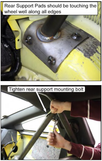
34. Mark the position of the four mounting holes in each rear support mounting pad onto the wheel well using a center punch.
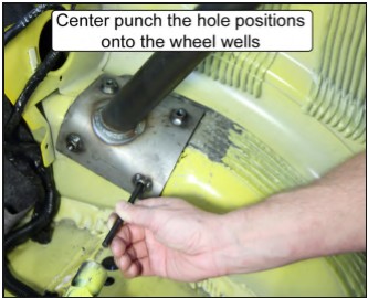
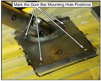
35. Mark the position of the four mounting holes in each door bar mounting pad onto the floor pan using a center punch.
NOTE: One of the mounting holes is located beneath the door bar tubing on each pad. Use a marker or small metal scribe to mark the hole location.
NOTE: Make sure the pad is resting against the rocker panel before marking the holes.
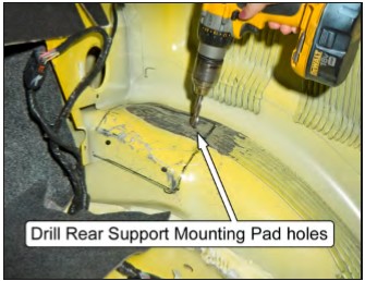
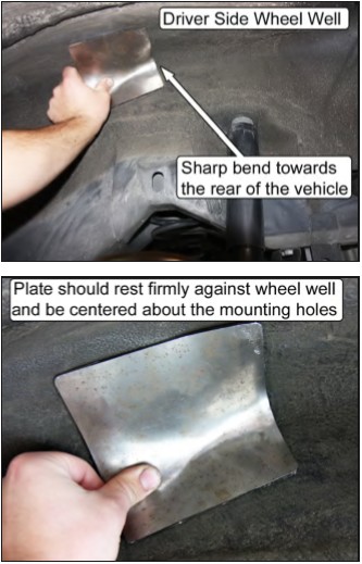
36. Remove the roll bar from the vehicle and drill the four holes marked on each wheel well out to a 7/16” diameter. Use ~1/8”-diameter pilot drill to start the holes.
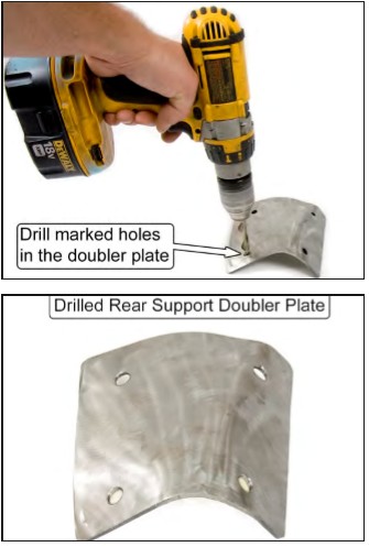
37. Hold the driver-side rear support doubler plate up into position against the bottom of the wheel well, centered under the four mounting holes.
38. With the doubler plate held in position, have someone mark the location of the mounting holes from the inside of the vehicle using a center punch or marker.
39. Drill out the holes in the doubler plates to 7/16” diameter and set them aside for later installation.
40. Repeat Steps 37-39 for the passenger-side rear support doubler plate.
Door Bar Mounting Holes
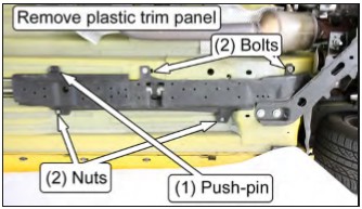
41. Remove the plastic trim panel on the underside of the floor pan, beneath the driver seat, that protects the fuel/brake lines and fuel filter. Use a 10mm-deep socket to remove the two hex nuts and two 10mm hex head bolts, and pliers to remove the one push-pin that secures the panel.
42. CAREFULLY drill down (from above) the four holes marked for each door bar mounting pad out to a 7/16” diameter.
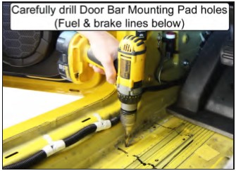
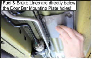
NOTE: There ARE fuel and brake lines directly beneath the driver-side door bar mounting pad. Place the door bar doubler plate between the underside of the floor pan and the lines (as a shield) when drilling to prevent puncturing the lines.
Plastic Quarter Panel Modifications
The plastic quarter panels have to be modified to allow the roll bar and rear supports to pass through. Use the following steps to properly trim the panels.
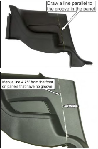
43. Using a straight-edge, mark a line down the plastic quarter panel that is aligned with the center of the vertical groove, toward the front of the armrest. If no groove is present, mark a line parallel to the front of the panel, approximately 4.75” rearward.
44. At the bottom of the quarter panel, extend the line across the horizontal flat. Add a mark about 3/8” forward of the line, centered side-to-side on the flat section.
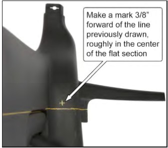
45. Using a 1-3/4” hole saw, cut a hole in the center of the flat, 3/8” forward of the marked line.
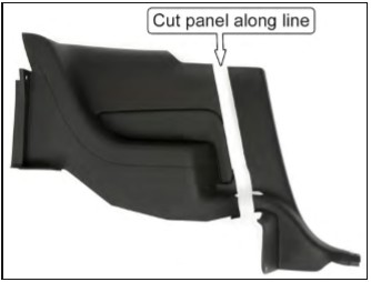
46. Cut the plastic quarter panel into two pieces, along the line that was drawn, using a wood saw or other cutting device.
47. Repeat for both sides.
48. Install the rear half of the driver-side plastic quarter panel.
49. Remove the driver-side rear support from the main hoop and place the hoop into the vehicle.
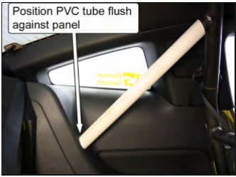
50. Fit the supplied PVC template onto the driverside rear support spud.
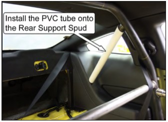
51. Set the roll bar back in its mounting position and slide the PVC tube down until it contacts the plastic quarter panel. Rotate the PVC tube so the end is parallel to the face of the panel.
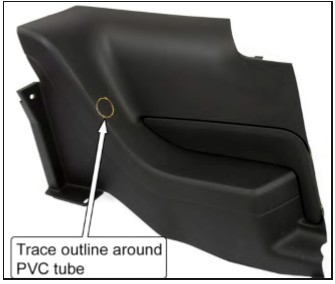
52. Use a marker to trace around the PVC tube, the location where the rear support will pass through the plastic panel.
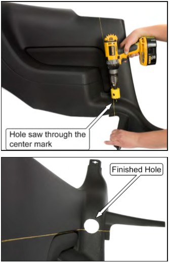
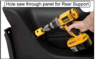
53. Remove the rear half of the plastic panel from the vehicle and hole saw through the location marked for the rear support. Use a 2” hole saw if available, or you can use a 1-3/4” hole saw to file the opening out larger.
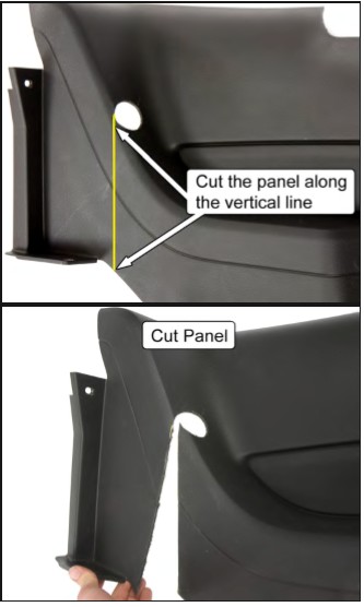
54. Cut a vertical line from the bottom of the plastic panel up to the rearward edge of the hole. This will allow the panel to slide onto the rear support during installation. Use sandpaper or a file to remove any burrs from the edge of the plastic panel.
55. Repeat Steps 49-54 for the passenger side of the vehicle with the driver-side rear support installed and the passenger-side rear support removed.
Do you want to die? If not, pay attention to this:
The rear braces must be welded to the main hoop. That step is not optional. The rear spuds are not structural; they are there only to align the rear braces to the main hoop for easy welding. If the rear braces are not welded to the hoop and the car rolls over, you will probably be killed because the spuds will break off the hoop and allow the roll bar to collapse. Follow the instructions and properly weld the rear braces to the main hoop. Check the MM Facebook page and website for a graphic example of how good the MM roll bars are when properly installed.
Welding the Rear Supports
56. With both rear supports attached, place the roll bar back into its mounting position and verify that all of the holes for the main hoop and rear support mounting pads line up with the holes in the vehicle. We highly recommend inserting all the mounting bolts to guarantee the holes line up.
57. Tighten the bolts holding the rear supports to the rear support spuds so the supports can’t move.
58. Remove the roll bar from the vehicle, with the rear supports firmly attached.
59. With the roll bar out of your car, have a qualified welder use either the MIG or TIG welding process to weld the rear braces to the main hoop.
The stubs that the rear braces bolt to are there only to properly locate the rear braces. They are not structural. Take care to have the rear braces welded to the main hoop itself, and not just to the locating stubs.
Take care to keep welding warpage to a minimum to ensure the roll bar fits back into the car properly. Welding must be free of any slag and/ or porosity. The NHRA prohibits any grinding of welds.
NOTE: If desired, remove the bolts from the rear supports and plug weld the holes shut once the supports have been welded to the main hoop.
Painting the Roll Bar
60. We recommend painting or powdercoating the roll bar and its components to protect them from rust. Do NOT grind on any of the welds when prepping the roll bar for paint.
NOTE: If the barrel-shaped portion of the door bar mounting spuds are painted or powdercoated, the INNER DIAMETER OF THE DOOR BAR MAY NEED TO BE ENLARGED slightly so that the door bar may slide over the spud. Use a round file or sandpaper to help enlarge the inner diameter.
Quarter Panel Connecting Plates
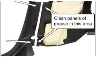
61. Clean the back of both halves of the plastic quarter panels along the cut line at the large flat area near the top, and the bottom flat area. Use acetone or isopropyl alcohol to remove any grease or mold release.
NOTE: Hold the connecting plates in position and use a scribe to mark the outline of the connecting plates onto the panels. Only this area needs to be cleaned.
62. Open ONE of the provided 3M Adhesion Promoter applicator packets and coat the areas cleaned in the previous step using the foam applicator. Once the areas have been coated, allow the adhesion promoter to dry for 1-2 minutes. NOTE: The temperature must be 70°F or higher for the best results.
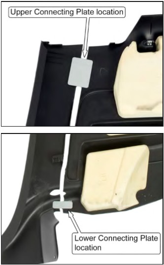
63. Remove the plastic backing from the foam tape strips on the connecting plates. Adhere the connecting plates to the upper and lower prepped areas of the rear half of each quarter panel. Press down firmly for a few seconds on each connecting plate to help the adhesive stick.
64. Repeat Steps 61-62 for the forward half of the plastic panels using the remaining 3M packet.
65. Remove the plastic backing from the Velcro® strips and align the two pieces of the quarter panel together. Once aligned, press down firmly for a few seconds on each connecting plate to help the adhesive stick.
66. Let the panels sit for about 30 minutes before any further handling. If the temperature is below 70°F, allow extra time for the adhesive to cure or put the panels indoors.
67. Separate the front and rear halves of the quarter panels by CAREFULLY pulling them apart at the Velcro.®
Final Installation
NOTE: Have at least two people help when setting the roll bar into its final position, and be patient.
68. Wrap the rear support tubes with something (such as tape, paper, or cloth) to protect them from scratches during installation.
69. Place the roll bar into the vehicle so the rear support mounting pads are resting on/near the MM support brackets and the main hoop pads are on the floor pan.
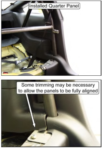
70. Install the rear half of the plastic quarter panels onto each of the rear supports by carefully spreading the vertical slit until the panels can slide onto the rear supports.
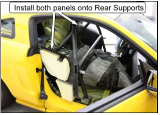
71. Lift the roll bar, along with the plastic panels, into position.
72. Reinstall all the mounting hardware for the main hoop and rear supports before tightening any of the bolts. The main hoop uses 3/8”-16 x 1”-long bolts with a 3/8” G8 washer under the bolt head. The rear supports use 3/8”-16 x 3/4”-long bolts and 3/8” G8 washers beneath the bolt heads.
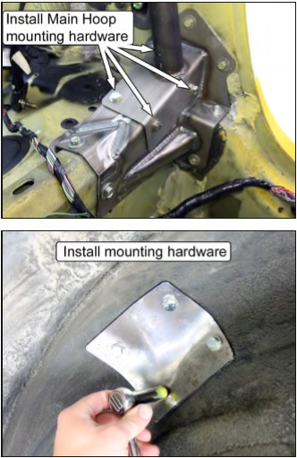
73. Torque the bolts to 33 lb-ft.
74. Attach the back half of the rear plastic quarter panels to the vehicle. There are two push-pin retainers on each panel located at the rear seat backrest. Be sure to engage the snap-in retainers located below the quarter window.
75. Place the wiring harness back into the stock location and reconnect the harness to the seat belt retractors (if disconnected in Step 14).
76. Unfold the carpet from the center console and place it back into position. Reinstall the two push-pins located on the rear seat bulkhead.
77. Attach the front half of the rear plastic quarter panels. Install the 1 push-pin retainer to secure each quarter panel to the rear seat bulkhead.
NOTE: Installation is easier if the panel is correctly positioned before the Velcro® is stuck together. To do this, cover the Velcro® strips with paper (temporarily secure the paper to the panel using tape); position the panel; then remove the paper. Press the two Velcro® strip halves together.
78. Reinstall the safety belts to the rocker panels and torque the T-47 Torx bolts to 30 lb-ft (40Nm).
79. Reinstall the rear seat backrest cushions. Torque the two 13mm hex head backrest bolts to 17 lb-ft (23Nm).
NOTE: MM roll bars with a fixed harness mount and/ or a diagonal brace do not allow the rear seats to fold down. Install the seat backrest cushions in the upright position before tightening the mounting bolts.
80. Reinstall the rear lower seat cushion.
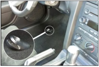
81. Temporarily install the door bars onto the door bar spuds and trim a hole in the carpet for each door bar. The trimmed carpet is shown below.
NOTE: Door bar removed for clarity.
82. Remove the door bars.
83. Reconnect the battery.
84. Reinstall the front seats; installation is the opposite of removal in Step 1. Torque the bolts and nuts to 35 lb-ft (48Nm).
85. Install the door bars using 3/8”-16 x 2 ¼”-long bolts and 3/8”-16 Nylock nuts for the upper connection to the roll bar and the 1/2”-13 x 1 ½”-long bolts and ½” G8 washers for the lower connection to the door bar mounting pads. Do not tighten the bolts yet.
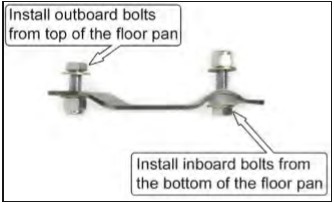
86. Secure the door bar doubler plates to the door bar mounting pads using the following hardware:
• Use 3/8”-16 x 1"-long bolts, 3/8”-16 Nylock nuts, and 3/8” G8 washers beneath the bolt heads and nuts for the two outboard mounting holes.
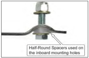
• Use 3/8”-16 x 1 ¼”-long bolts, along with the provided half-round spacers, 3/8”-16 Nylock nuts, and 3/8” G8 washers beneath the bolt heads and nuts for the two inboard mounting holes.
87. Torque the entire door bar mounting pad hardware to 33 lb-ft.
88. Torque the 1/2”-13 x 1 ½” bolts that connect the lower half of the door bar to the door bar mounting pad to 78 lb-ft.
89. Torque the 3/8”-16 x 2 ¼”-long bolts and 3/8”-16 Nylock nuts that connect the upper half of the door bar to the main hoop.
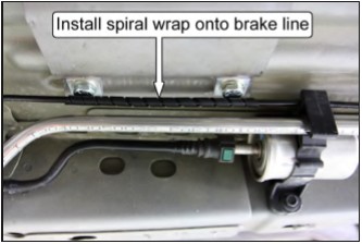
90. The outboard brake line will touch the heads of the door bar mounting hardware. Wrap the provided spiral wrap onto the brake line where it makes contact with the mounting hardware. Use the remaining two zip-ties to secure the wrap to the line.
NOTE: We recommend repositioning the line(s) to avoid any contact with the bolt heads. This can be done by bending them slightly.
91. Install the plastic trim panel removed in Step 41 that protects the fuel/brake lines and fuel filter. Torque the 10mm hex head bolts and nuts to 5 lb-ft (7Nm).
92. Make sure the forward half of the carpet is back in position.
93. Install the plastic kick panels and secure each one with a plastic push-pin.
NOTE: Reinstall the alarm switch into the passenger-side kick panel if it was removed in Step 12.
94. Install the door scuff plates.
95. Reinstall the rear wheels and safely lower the vehicle to the ground. Torque the lug nuts to the manufacturer’s recommended value.
NOTE: Roll bar padding must be installed on any areas of the roll bar that the vehicle occupants may possibly contact during an accident. This includes any parts of the roll bar that the occupants’ hands, arms, legs, head, and feet may contact.
Door Bar Removal
When the door bars are not needed, they can easily be taken out of the vehicle by removing the bolts attaching the upper and lower halves of the door bar to the main hoop and the door bar mounting pads. Once the bolts are removed, swing the bottom of the door bars inward to clear the lower mounting pads and pull them forward to detach from the door bar mounting spuds.