 FREE 1 to 3-Day Delivery on Orders $149+ Details
How to Install Maximum Motorsports Adjustable Front Sway Bar (94-04 All) on your Ford Mustang
Installation Time
2 hours
Tools Required
- Standard assortment of hand tools
- Torque wrench

Shop Parts in this Guide
Read all instructions before beginning work. Following instructions in the proper sequence will ensure the best and easiest installation.
Supplemental Installation Notes
• The MMFSB-32 Adjustable Endlinks are only designed to work with the MMFSB-31 Front Swaybar.
• Proper installation of the swaybar endlinks requires the vehicle to be at ride height, with the full weight on the tires. This can be achieved by using a drive-on lift or safely placing the tires on evenly stacked plywood boards.
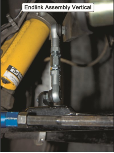
• The endlinks should be as close to vertical as possible when the vehicle is at ride height. Because of the multiple mounting positions possible, it is the responsibility of the installer to correctly orient the endlinks.
Required Supplemental Items
• MMFSB-31 Adjustable Front Swaybar
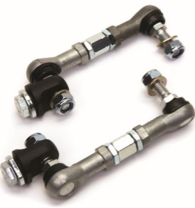
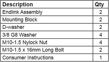
This Kit Contains
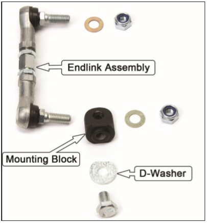
Component Identification
Installation
For proper installation, one with zero suspension preload from the front swaybar, the vehicle must be on a drive-on lift or other flat and level surface that allows access to install the endlinks. The weight of the vehicle must be resting on the tires. Using jack stands is not an acceptable compromise.
If the endlinks must be installed with the suspension at full droop, we recommend setting the endlink assemblies to the same length before installing them on the car.
1. Starting with the passenger side, install the Mounting Block into the swaybar mounting hole, on top of the lower control arm.
NOTE: When using MM Front Control Arms, insert the Mounting Block in the outer swaybar mounting hole. Using the inner mounting holes will reduce the effective wheel rate.
2. Place a D-washer onto one of the M10-1.5 x 16mm long bolts. Thread the bolt upwards through the control arm hole for the endlink, and thread it into the Mounting Block. Do not fully tighten the bolt. Leave it just loose enough that the Mounting Block can be rotated on the control arm.
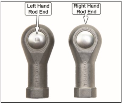
3. Take an endlink assembly and insert the right hand rod end through the Mounting Block. Secure it with a provided washer and M10-1.5 Nylock nut. Torque the nut to 33 lb-ft.
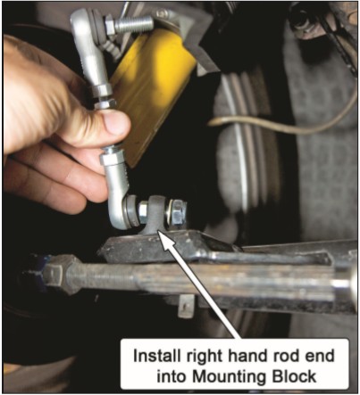
NOTE: The left hand rod end will have an “L” stamped into the metal cap securing the threaded stud.
4. Insert the free end of the endlink assembly into the desired mounting hole on the swaybar. Secure it with a provided washer and M10-1.5 Nylock nut. Torque the nut to 33 lb-ft.
NOTE: The endlink assembly should be as close to vertical as possible. Adjust the orientation of the upper and lower rod ends as needed to achieve this.
5. With the endlink assembly correctly oriented to position it as vertical as possible, secure the Mounting Block to the control arm by tightening the M10-1.5 x 16mm long bolt to 33 lb-ft. The mounting block must be rotated to aid in making the endlink vertical.
NOTE: Wrench flats are provided on the Mounting Block to prevent rotation while torquing the bolt.
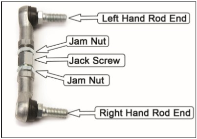
6. The jack screw is the threaded rod with a hex in the middle that connects the two rod ends together. Rotating this screw will either shorten or lengthen the endlink assembly. Shorten the assembly as much as possible.
Rod End Clocking Procedure
It is critical for both rod ends to have as much angularity as possible. This requires the upper and lower rod ends to be centered in their range of angularity. Use the following steps whenever adjusting the endlinks. Please note, these steps require the right hand threaded rod end to be attached to the Mounting Block.
7. Tighten the lower jam nut against the lower rod end using wrenches on the rod end and the jam nut.
8. Hand Tighten the upper jam nut against the upper rod end. It will be fully tightened in Step 11.
9. Looking up from the underside of the car, use a wrench to rotate the upper rod end counterclockwise until it stops. Hold it in that position and continue to the next step.
10. Rotate the jack screw/lower endlink counterclockwise until it stops. Use a wrench if necessary.
11. With the entire endlink assembly rotated counterclockwise, tighten the upper jam nut against the upper rod end using a wrench on the jam nut and the upper rod end.
NOTE: The upper rod end threads are left hand. The jam nut should be rotated counterclockwise to tighten it.
12. If done correctly, the endlink assembly should be free to rotate ~ 45° along it’s axis.
Driver Side Installation
There should be no load passing through the swaybar endlinks while the vehicle is at rest on flat, level ground. Any load passed between the swaybar arm and the control arm causes the swaybar to be “preloaded.” Any swaybar preload will alter the corner weights of the vehicle, which in turn affects handling behavior.
Swaybar preload is created when the second endlink to be attached is either to short, or too long, to connect the swaybar to the control arm without needing to force the swaybar arm from its relaxed position into a new position. The length of the driver side endlink should be adjusted so that it can be freely installed, without needing to push the swaybar arm up or down to insert the rod end studs into the holes on the swaybar lever arm and the Mounting Block.
13. Repeat Steps 1-12 on the driver side. Adjust the length of the endlink assembly so that it freely installs into the swaybar mounting holes.
NOTE: If the driver side endlink is too long to freely install, the passenger side endlink must be lengthened first. To do so, loosen the jam nuts on the passenger side endlink. Rotate the jack screw one revolution (or more if needed) to lengthen the endlink, and repeat the Rod End Clocking Procedure.
14. Test drive and enjoy.
