 FREE 1 to 3-Day Delivery on Orders $149+ Details
How to Install Maximum Motorsports Caster Camber Plates on Your 2005-2010 Mustang
Installation Time
4 hours
Tools Required
- Lug Wrench
- 21mm Deep Socket
- 18mm Deep Socket
- 15mm Deep Socket
- 17mm Socket
- 13mm Socket
- 10mm Socket
- Torque Wrench (requires 166lb-ft capacity for strut-to-spindle nuts)
- Floor jack
- (2) Jack stands
- Spring compressor
- Wheel chocks
Shop Parts in this Guide
Installation
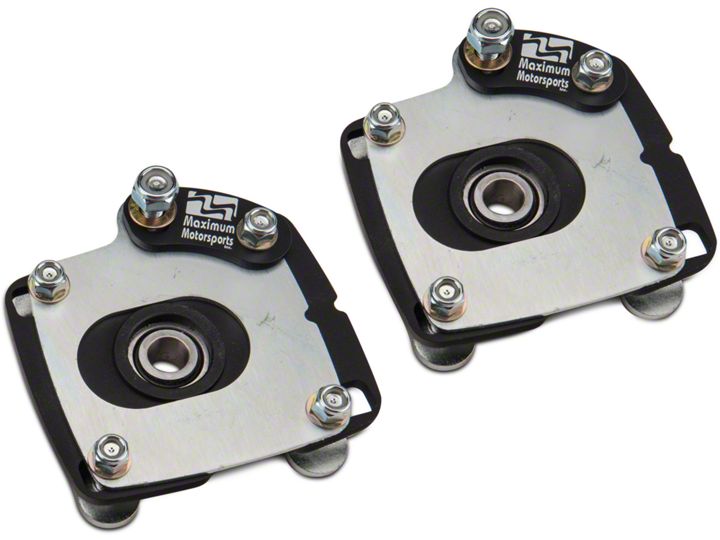
Package Contains:
- (2) Camber plates (black plates with slots and spherical bearing)
- (2) Caster plates (thing silver plates with slots)
- (2) Upper spring perches (dish-shaped circular pieces, with plastic center)
- (2) Support brackets (curved plates with one hole and one slot)
- (4) Stud plates
- Bag of hardware
Installation Instructions:
1. Open the bag of hardware and find the (4) tapered spacers. Each black camber plate will take (2) of the tapered spacers. Install them into both sides of the spherical bearing, ensuring that they are fully pressed into the bearing (this will require some force if the spacer is not seating against the bearing).
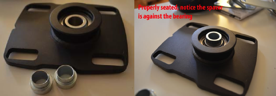
2. Once both sides of the bearing have a taper, do the same for the other caster plate. During the rest of the guide, make sure these don’t fall off the plate.
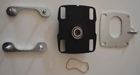
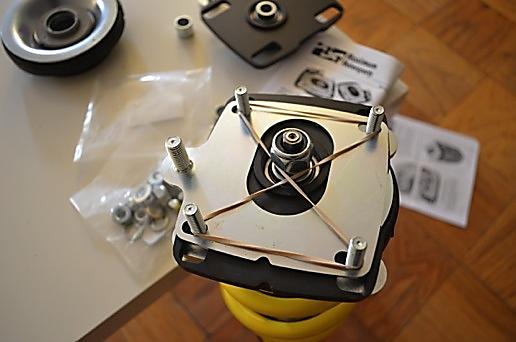
3. Line up the plates, studs and rubber band as shown on a flat surface:
4. Assemble in the following order: Place the camber plate (black) onto the (2) stud plates. Notice that the stud plates have a “U” shape and they point inwards. Also take notice that the camber plate has the bearing protruding on one side only, this side must face down.
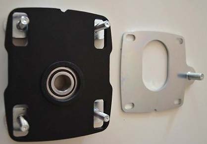
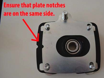
5. Place the caster plate (silver) on top of the camber plate (black) and through the studs. The center oval slot will fit exactly into the center circle of the caster plate. Note that while there is no driver/passenger side differentiation, the (2) notches must match up for correct orientation.
6. Attach rubber band and cross it once to keep tension on the studs. This stops the assembly from falling apart when you install it. The rubber band will not be removed until the plate is installed onto the actual car.
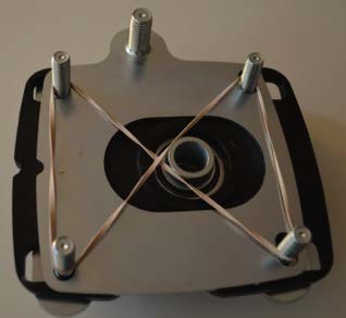
7. The plate assembly is now complete; do the same for the other plate.
8. Loosen the lug nuts on both front wheels. Do not remove lug nuts, simply loosen them. Engage the parking brake and use wheel chocks on rear wheels.
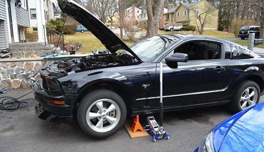
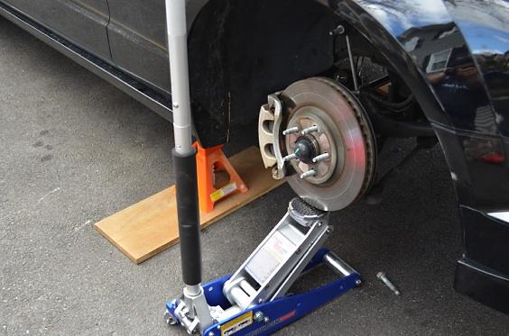
9. Jack up your mustang by the frame rails and use jack stands to support the vehicle. Remember that there are (2) “slots” along the frame rail on each side of the car. We will use the (2) front ones, which allow a jack stand to be used with the frame rail without damaging the side skirts. The following picture shows where you should place your floor jack and your jack stands. Raise the car until the wheels are off the ground and secure it with a jack. DO NOT SUPPORT THE CAR WITH THE JACK, ALWAYS USE JACKSTANDS FOR SAFETY. Raise both sides to unload the front suspension completely.
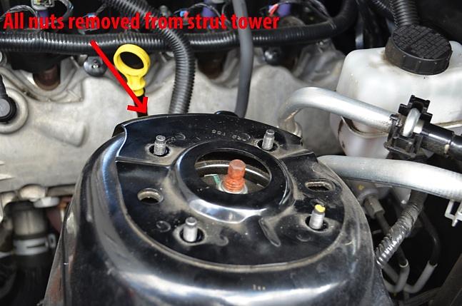
10. Remove both front wheels to reveal the strut assembly. The strut assembly is attached by (2) bolts and nuts on the wheel hub. It is attached to the chassis with (4) nuts at the strut tower (under the hood). But before we remove the strut, we need to remove the ABS line, brake bracket, and the swaybar end link, which are all attached to the strut.
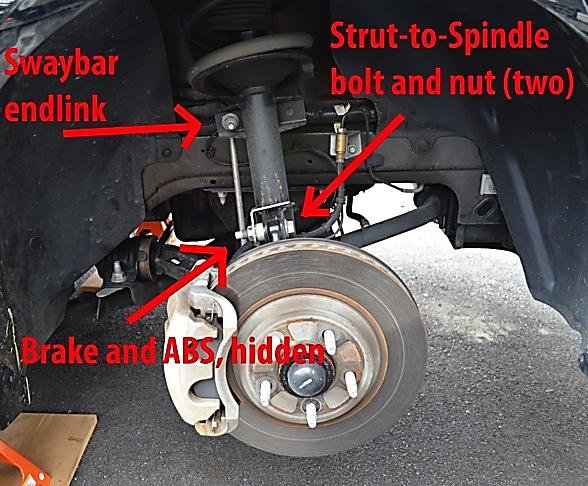
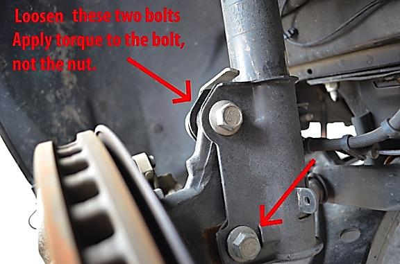
11. Loosen the (2) bolts using an 18mm socket, but do not remove. NOTE: Ford lists these parts as one-time use. It is recommended to buy new hardware from your local Ford dealer or online to replace the four (2 per side) strut-to-spindle bolts.
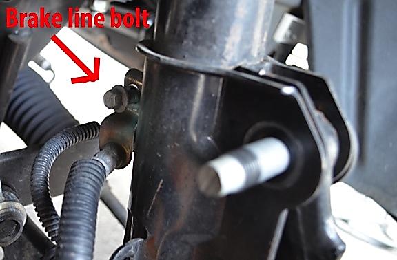
12. Remove the brake line bracket from the strut; this is held in by a single 10mm bolt.
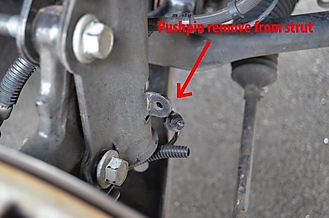
13. Remove the pushpin from the strut to free the ABS line from the strut.
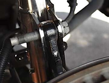
14. Remove sway bar end link by loosening and removing the bolt that holds it to the strut. Use a 15mm deep socket here as a shallow socket will not work.

15. Use your floor jack to support the hub assembly. When you remove the strut, the hub will be unsupported and would otherwise fall to the ground. To avoid this, gently support the hub by the brake rotor. You can also support the suspension arm if you prefer.
16. Loosen and remove all (4) bolts from the top strut mount using a 13mm socket.
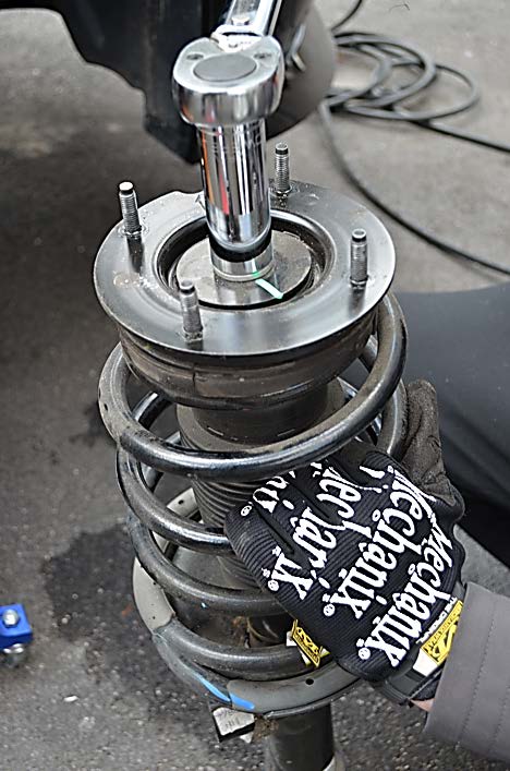
17. Note that the chassis no longer supports the strut. Its weight is on the hub, which is on the floor jack. Remove the (2) spindle-to-hub bolts from the bottom of the strut using an 18mm socket. Do this carefully while supporting the strut with your other arm (a friend is helpful for this step). You may need to raise and lower the jack to line up the strut and hub in order to get the bolts out. After a bit of wiggling, you will get the (2) bolts out and the entire strut and spring assembly will be free from the car. Carefully remove it from the vehicle (it is heavy!) and leave the jack to support the rotor.
18. Strut disassembly: Use the spring compressor to compress the spring on the strut. Please refer to spring compressor instructions for details. Once compressed, remove the top 21mm nut. This will disassemble the entire strut assembly so that the top strut mount can be removed.
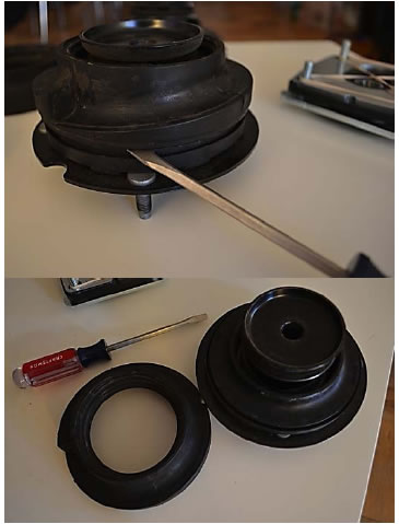
19. Once removed, disassemble the top mount by removing its rubber spring isolator. Use a flathead screwdriver to pry it off gently. You will reuse the rubber spring isolator part of the factory strut mount.
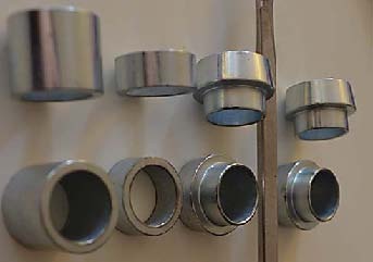
20. With the spring still compressed and the top mount off, locate the rest of the spacers. The following is a picture of the types of spacers you should have, viewed from both angles. Note that we’ve already used the (4) tapered spacers on the camber plates (the 2 rows on the right of the picture). The remaining spacers have (2) types: (1) long and (1) short.
21. Slide the long spacer first so that it is below the short spacer, as shown. Note: the pictures show an aftermarket suspension, but the process is exactly the same with factory suspension or just about any bolt-on suspension. The piston rod is 22mm in diameter, which is typical.
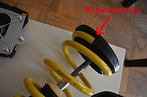
22. Now place the rubber spring isolator that we removed from the factory strut mount on your spring. Make sure that the rubber lines up with the end of the spring coil.
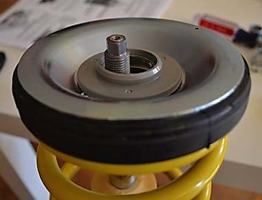
23. Once the rubber spring isolator is lined up, place the metal dish-shaped plates on top of the rubber isolator. This should fit in place as shown. NOTE: the piston rod will not be centered and will be free to move around at this point. Your end result may look slightly different depending on how much you compressed the spring. If the piston rod does not stick out past the plate, you will have to compress the spring more. You need to be able to thread the top nut onto the piston rod with the spring compressed.
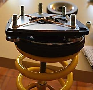
24. Now place your assembled camber caster plates on top of the metal dish. Note that the protruding spherical bearing faces down and the studs face up. The bottom of the camber plate (black) will fit perfectly around the plastic ring shown in the previous picture. Make sure that both tapered spacers are still seated in the spherical bearing when you put the plates on. The piston rod will fit through the tapered spacers and through the spherical bearing.
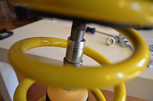
25. Tighten the top strut nut back onto the piston rod using a 21mm socket. IMPORTANT: Refer to your shock manufacturer for torque specifications. Each shock manufacturer has different torque recommendations for the top strut mount. OEM spec is 45 ft/lbs. You may need to clamp the piston rod if it rotates. Be sure not to damage the piston rod during this process; vice grips with towels for padding works well.
26. Once the top nut is properly tightened, slowly decompress the spring by releasing the tension on the spring compressor. Ensure that everything is lined up as the spring expands. Make sure the rubber spring isolator on the top is lined up with the end of the spring coil. Also make sure that your spring is properly seated into the strut at the bottom.
27. Repeat the same process for the other strut. Both of your strut/spring assemblies will then be ready for installation into your car.
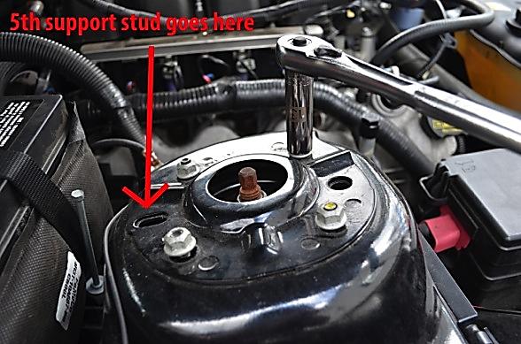
28. To prepare the strut for assembly, make sure the bottom mount is facing toward the outside of the car (because that is the side that will bolt up to the hub). At the same time, notice that the camber caster plates can rotate freely on the top of the strut. This is normal; you should rotate the assembly until the (2) notches face towards the outside of the car. To make sure, you will notice that the camber caster plates have (5) studs, instead of the (4) on the OEM mount. The 5th and largest stud is a support stud. It will be the rearmost stud on the plate and fits through the slot on the strut tower rather than the extra hole. If the 5th stud is in the right place, you will note that the notches are also facing towards the outside of the car. This is a good way to double check that you have the correct orientation.
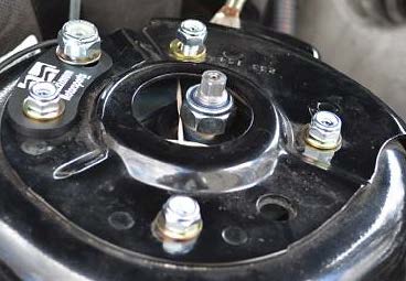
29. A friend is helpful for this step. Insert the strut assembly back into place until the studs comes out of the strut tower. Secure the strut to the chassis by using the supplied nylon locking nuts and washer. You’ll notice you have (8) small nuts and washers and (2) large nuts and washers. The small ones (13mm) are for the 4 studs and the large ones (17mm) are for the larger support stud. Secure the nuts onto the (2) front studs, simply hand tighten them and you can let go of the strut (it is now supported by the chassis so you can rest your arm). Secure the other nuts but make sure to install the support bracket first. Your result should look similar to this:
30. Gently tighten all the nuts using the 13mm (small) and 17mm (large) sockets. You do not need a specific torque at this point; simply gently tighten them with a socket wrench. We will come back and loosen them later for adjustment.
31. Now, reattach the bottom of the strut to the hub using an 18mm socket. It is recommended to use new OEM hardware here, as per Ford specifications. Remember to use the floor jack to support and adjust the hub height in order to slide the strut into position.
32. Tighten to factory specification, which is 166 ft/lbs, as per Ford’s new hardware; they switched to a fine thread from the coarse thread, which had a lower torque specification of about 150 ft/lbs. It is highly recommended to get the new hardware.
33. Reattach the brake line bracket to the rear of the shock with the 10mm bolt.
34. Reattach the pushpin holding the ABS line. Reattach the swaybar link to your shock body with a 15mm deep socket, torque to 85 ft/lbs.
35. Your strut assembly is now secured back onto the car. We need to set the camber and caster (by a rough guess) at this point.
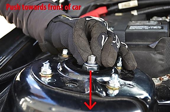
36. Loosen all (5) top nuts just enough so that you are able to slide the strut (13mm and 17mm sockets). Push the rod from the top of the tower all the way forward toward the front of the vehicle. You can also reach down into the wheel well and push on the strut directly.
37. Once the strut is pushed all the way forward, tighten the largest support nut using a 17mm socket to 26 ft/lbs. This is the caster adjustment.
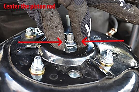
38. Center the strut in the strut tower regarding left/right orientation. This is the caster adjustment.
39. Once centered, tighten the remaining (4) nuts using a 13mm socket to 20 ft/lbs.
40. Double check that you have tightened:
a. Both strut-to-spindle bolts and nuts on the bottom of the strut.
b. The brake line bracket.
c. The ABS line plastic pushpin.
d. The swaybar endlink.
e. All (5) nuts on the top of the strut tower.
41. Repeat the same steps for the other side of the vehicle.
42. Once both sides are secured, put the wheels back onto the car and tighten the lug nuts.
43. Jack up the car and remove the jack stands; gently lower the car to the ground onto the tires.
44. Torque all lug nuts in a star pattern to 100 ft/lbs (this may vary for aftermarket wheels).
45. Your installation is complete.
CASTER/CAMBER ADJUSTMENT:
NOTE: It is recommended that the car is aligned by a professional or with the use of a caster/camber gauge.
1. Caster adjustment is ALWAYS done before camber adjustment with these plates.
2. To adjust caster, jack up car and secure with jack stands. The front suspension must be unloaded for adjustments.
3. Loosen all (5) top mount nuts (13mm and 17mm sockets) just enough so that the strut can slide, just like we did during the installation.
4. Sliding the piston rod forward or backwards will adjust the caster.
5. Once set, tighten the support (largest) nut to 26 ft/lbs using a 17mm socket.
6. Your caster is now set.
7. Notice that you can still shift the piston rod left and right. This is how you set your camber. Sliding it towards the inside of the car will create more negative camber.
8. Once set, tighten the rest of the (4) nuts to 20 ft/lbs using a 13mm socket.
9. Your camber is now set.
10. If you want to adjust camber only without affecting caster, simply loosen only the (4) smaller nuts on the top of the tower with the 13mm socket. The 5th larger nut will stay tighten and ensure that caster does not change while you adjust camber.
Installation Instructions written by AmericanMuscle customer Billy Zhang 4.11.12
