FREE 1 to 3-Day Delivery on Orders $149+ Details
How to install an MSD Ignition Controller on your 1996-2010 Mustang

Shop Parts in this Guide
Installation
Parts Included
Optional Accessories
- 1 - Ignition Controller, PN 6011
- 1 - Pro-Data Software CD
- 1 - Harness
- 1 - Parts Bag
- 1 - 2-Bar MAP Sensor
- Hand Held Monitor, PN 7550
- EFI Harness and Tach Adapter Kit, PN 88814
Warning: During installation, disconnect the battery cables. When Disconnecting, always remove the Negative cable first and install it last.
Note: Solid core spark plug wires or non-resistor spark plugs cannot be used with an MSD Ignition Control.
CARBURETOR
The PN 6011 Ignition Controller is designed for Ford Modular engines that have been retro-fit with an intake manifold and carburetor. The Controller is supplied with a wiring harness that connects to the factory connectors for a simple installation.
EFI
This Controller can also be used in stock EFI applications, by using accessory Harness PN 88814. This Harness allows the PN 6011 Controller to tap into the sensor signals without interrupting the OEM ECU. The ECU and coils operate as normal while the PN 6011 controls the timing and rpm. When using with an EFI system, a tach adapter harness will be required, PN 88813.
OPERATION
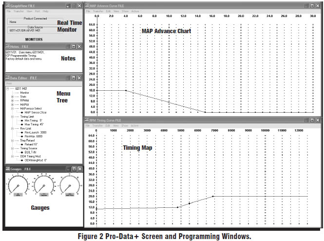
The MSD Controller offers several programmable features that allow rpm and timing adjustments. This can be achieved through the supplied Pro-Data software via a PC or with the optional Hand Held Programmer, PN 7550. Timing adjustments and selections can also be made with plug-in modules. Software installation, operation and the programmable features of the Controller are explained in detail in this document. More information can be found in the Pro-Data Software Help section.
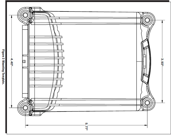
MOUNTING
The Controller is designed to be mounted under the hood or on the firewall. Do not mount the unit near exhaust. Find a suitable location, confirm that all of the wires reach their connections. Mark the mounting hole locations using the unit or the template shown in Figure 3, page 7. Drill the holes with a 3/16" bit.
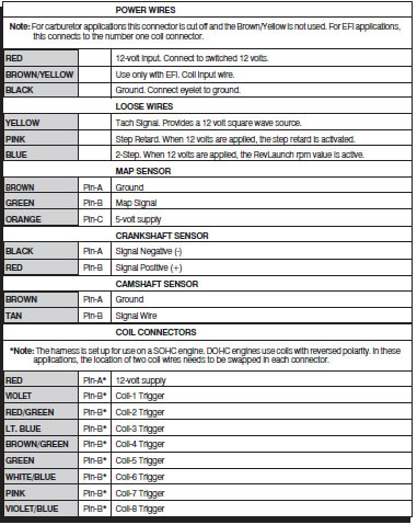
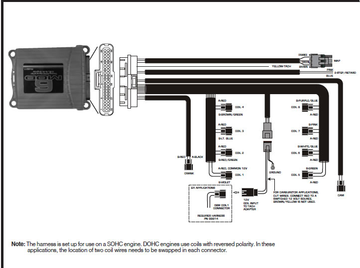
WIRING
All of the wiring, except four wires, are routed into factory style connectors to ensure an easy installation on a SOHC engine. On DOHC engines the coil polarity is reversed. In these applications, the coil wiring needs to be relocated. It is recommended to look at the polarity markings on the coil to confirm the polarity. The wire descriptions follow in the chart on page 2.
PROGRAMMABLE FEATURES
The following explains the programmable features of the PN 6011 Controller. The features are listed in the same order shown on the Data Editor list in the software. Note that the Help pull down menu of the software offers explanations of all the features.
Note: STAT S Stat 1 or SCAN are display features only used with the Hand Held Monitors, PN 7550 or PN 7553.
RPM TABLE (RPMtbl)
This setting can only be modified from the RPM Timing Curve edit graph on the lower right of the screen (It can also be set with the Hand Held Monitor). The chart allows you to map out an entire timing curve, much like the centrifugal advance of a mechanical distributor.
To create a map, simply position the mouse at a point on the chart and right click to add a dot. Up to 10 points can be added. By moving the mouse over this point and a left click, the dot changes to red (active) and you can move it around the map by clicking and dragging.
Note: The timing has minimum and maximum limits that are set in the Data Editor Menu. These settings include the cumulative value of any vacuum advance or retard as well as the Switch Retard if used.
MAP TABLE (MAPtbl)
Note: In order to take advantage of a vacuum advance, a MAP sensor is required.
This is a Manifold Absolute Pressure (MAP) chart. It gives you the capability of modifying the timing curve based on manifold pressure (vacuum or boost). A curve can be created from the MAP Advance Curve graph on the upper right of the screen (It can also be set with the Hand Held Monitor). The chart allows you to map out an advance curve based on manifold vacuum (much like the vacuum advance on a mechanical distributor).
To create a map, simply position the mouse at a point on the chart and right click to add a dot. Up to 10 points can be added. By moving the mouse over this point and a left click, the dot changes to red (active) and you can move it around the map by clicking and dragging.
Note: The timing has minimum and maximum limits that are set in the Data Editor Menu. These settings include the cumulative value of any vacuum advance or retard as well as the Step Retard if activated.
MAP SENSOR SELECT
Allows the selection of a 1, 2 or 3-bar MAP sensor. This setting should be set to match the MAP Sensor in use: 1-bar (0-15 psia), 2-bar (0-30 psia), 3-bar (0-45 psia). A 2-bar Sensor is supplied.
TIMING LIMIT
There are two adjustments that set the limits of ignition timing. These settings are meant as safety targets to keep the timing in check. Both the Minimum and Max values include any timing retards or advancements.
Min Timing This is the minimum amount of timing advance. It is adjustable from 0°-20° BTDC with a default of 5°.
Max Timing This is the maximum amount of timing advance. It is adjustable from 25°-65° BTDC with a default of 45°.
PRO-DATA
Installation of the Pro-Data Software
1. Insert the installation CD into your PC.
2. In Windows, click on Start then select Run.
3. In the box type, “D: Setup” and press Enter (or corresponding drive).
4. The screen will walk you through several steps.
5. Once loaded, your monitor will have an MSD Graph View logo. Click on it to open the software.
6. A program will open. Go to the upper left corner of the screen and click on File, then Open.
7. This will open a menu of part numbers. Select “6011”.
8. This will open another menu of versions. Highlight and open the “6011vxx.IGN” (xx determines the versions, such as 02). This will open the Pro-Data software for the Ignition Controller.
Saves and Transfers
Whenever a change is made to a program, it either must be saved to a file in your PC or it needs to be transferred to the Controller. You will notice that whenever you make a change to a program, the bullet next to the modified value will turn red. It will remain red until you save it to a file or to the MSD. There are two ways to save your files.
Save to MSD: This step will save any changes directly into the Controller. If you are only making one or just a couple modifications this works well.
Save to PC: This will save your changes to only show on the PC screen (indicated by a red bullet point next to any altered values). These modifications will not be active or saved until you save the file or transfer the information to the MSD.
You can create numerous files on your PC and download them for testing purposes or save programs you used at different races or events.
REV LIMITS
The Controller allows you to program two rev limits; one for an over-rev safety and another that provides a low limit for use as a launch, or two step limit.
RevLaunch This is the low rpm limit that is designed to be used while staged at the starting line. It is activated when the Blue wire is connected to 12 volts. When there is no 12 volts on this wire, the High Rev Limit is active. It is adjustable in 100 rpm increments from 2,000 - 12,500 rpm.
RevMax This is the high, or over-rev rpm limit. It is active whenever the Blue wire (RevLO) is not connected to 12 volts. It is adjustable in 100 rpm increments from 2,000 - 12,500 rpm.
STEP RETARD
A step retard will provide an adjustable amount of retard at a specific moment. This is ideal when using nitrous oxide. The amount of retard is adjustable from 0° - 15° in 1° increments. The retard is activated when the Pink wire is switched to 12 volts. Default is 10°.
TIMING SOURCE
This adjustment allows you to select a timing curve. The 6-Mod lets you run a Built-In default curve that can easily be modified by using the RPM Table chart. On engines using the factory EFI you can select OEM Advance or OEM Retard to use the factory ECU’s timing map.
Built-In: This is a general timing curve that is designed to work well with most stock type engines. This chart is shown in the RPM Table and MAP Table charts. These can easily be modified by clicking and dragging on the dots, or by adding a dot (right click) and saving to the ignition.
OEM Advance: This selection is used with a factory EFI equipped engine. The 6-Mod will use the factory ECU’s timing curve. By using the OEM Timing Mod option below, the entire timing curve will be advanced the amount you set.
OEM Retard: This selection is used with a factory EFI equipped engine. The 6-Mod will use the factory ECU’s timing curve. By using the OEM Timing Mod option below, the entire timing curve will be retarded the amount you set.
OEM timing mod
This option is available only when running the factory ECU’s timing curve on EFI equipped engines (Selected as OEM Advance or Retard). Here you set the total amount of advance or retard for the factory timing curve. The default is 0°.
OEMtimingmod: Adjustable from 0° - 10°.