FREE 1 to 3-Day Delivery on Orders $149+ Details
How to Install MSD Digital Window Switch on your Mustang

Shop Parts in this Guide
OPERATION
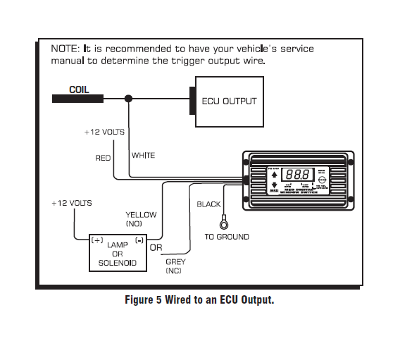
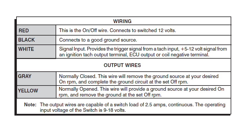
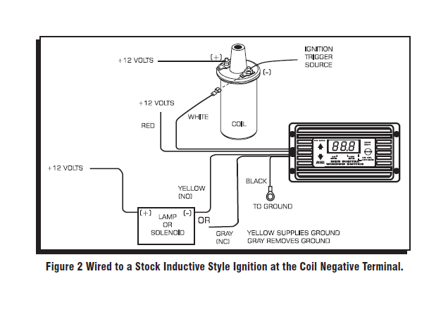
The MSD Digital RPM Activated Window Switch accepts a variety of input signals from sources such as a coil negative terminal (factory inductive ignitions), a CD ignition tach-output such as an MSD 6 or 7 Series Ignition, an output from an ECU, or a 5-400 volt signal from an MSD Tach Adapter.
The PN 8969 can be programmed for use on nearly every engine with a spark ignition or tachometer signal. The rpm values are adjustable in 100 rpm increments from 200 - 15,000 rpm (The rpm is shown x100). There must be a difference of at least 300 rpm between the two activation points for correct operation. Changes can be made while the engine is running.
Note: There is a 200 rpm safety range built into the activation and deactivation points. This means that the rpm must drop 200 rpm below the activation point to turn the circuit off. Conversely, the rpm must drop 200 rpm below the deactivation point in order to turn the circuit back on. This is to prevent the circuit from ‘chattering on and off’.
This switch is also capable of activating a circuit at a higher rpm than the Off rpm.
PROGRAMMING THE RPM
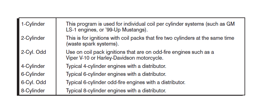
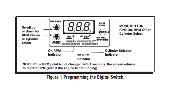
The engine application and rpm activation points are easily selected through push buttons on the LED panel (Figure 1). This Switch can be programmed for a variety of engine and ignitions as shown in the following chart.
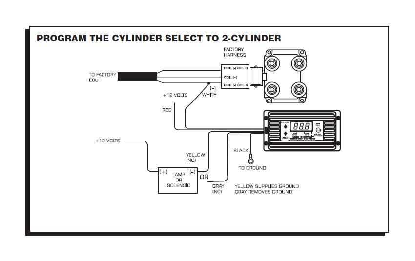
The rpm activation points and cylinder select are programmed through the push buttons on the LED panel (Figure 1). Press the Mode button, and notice that the indicator light above the On RPM lights. When that point is on, you can scroll the rpm value up or down with the arrows on the left of the panel. Once your On rpm is set, push the Mode button until the Off RPM point lights, then set the Off rpm point. Note that if the rpm point is not changed within 2-seconds, the screen returns to the current rpm reading (zero when the engine is not running). After setting the On and Off points, press the Mode button to program the Cylinder Select Valve (default is for 8-cyl.).

5 VOLT CONVERSIONS AND PIN LOCATIONS
On many DIS applications, you can connect the White wire to the ECU Tach Output. Following are suggested Pin locations. It is recommended to have your vehicle's factory service manual or wiring schematic.
Corvette
'97-'98 Pin 35 White wire of computer on right side of engine compartment below the battery tray. '99-'03- Pin 10 White wire of computer right side inner fender well.
Camaro-Trans Am-Firebird
'98 Pin 35 White wire of computer behind right strut tower. '99-'03 Pin 10 White wire of computer behind right strut tower.
Trucks-Suburban-Tahoe
'99-'03 4.8, 5.3, 6.0 and 8.1 engine's Pin 10 White wire of computer left front of engine compartment.