FREE 1 to 3-Day Delivery on Orders $149+ Details
How to install an MSD Power Grid System on your 1979-1995 Mustang

Shop Parts in this Guide
Installation
Parts Included:
- 1 - System Controller, PN 7730
- 1 - 2Gb SD Card
- 1 - Micro-USB Cable
- 1 - MSD View CD-Rom
- 1 - Fiber Optic Plug
- 1 - CAN Terminator Cap
- 1 - Power Cable-Loose
- 1 - Mag Cable
- 1 - 2-pin Legacy Cable
- 1 - Main Cable Loose
- 1 - Parts Bag
Accessories (Purchased Separately):
Inductive Cam Sync Kit, PN 7555
Hub Connector, PN 7740
Slew Rate and Time Based Rev Limiter, PN 7761
Boost Retard Module, PN 7762
Manual Launch Controller, PN 7751
Racepak V-Net Tee
9” - 280-CA-VM-T009
18” - 280-CA-VM-T018
36” - 280-CA-VM-T036
WARNING: During installation, disconnect the battery cables. When disconnecting, always remove the Negative cable first and install it last.
Note: Solid core spark plug wires cannot be used with an MSD Ignition Control.
Note: A crank trigger is recommended to supply the input signal to the Power Grid Ignition System to ensure the most precise timing and rpm control.
OPERATION
DIGITAL OPERATION
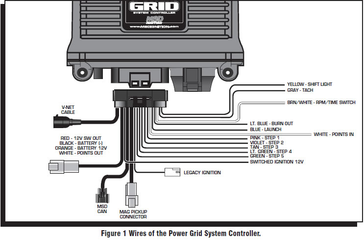
The MSD Power Grid System Controller uses a high speed RISC microcontroller to control the ignition’s output while constantly analyzing the various inputs such as launch, burnout, and step wires; trigger signals, rpm, and CAN-Bus data. The high speed controller can make extremely quick updates to the ignition output, timing, and rpm limits while maintaining /- 0.1° timing and /- 1 rpm resolution. The circuits and controller of this system have been designed for superior protection against Electro Magnetic Interference (EMI).
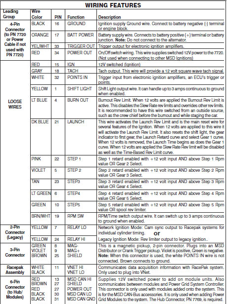
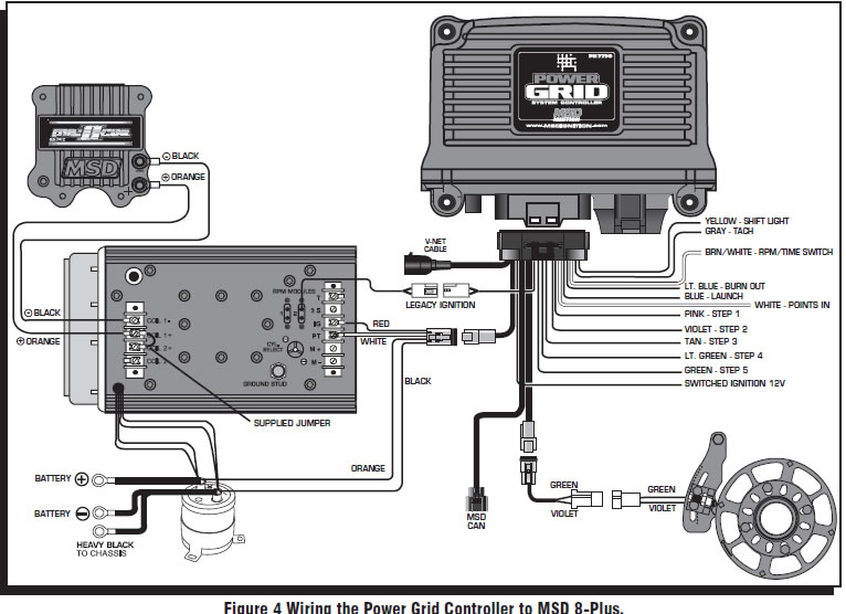
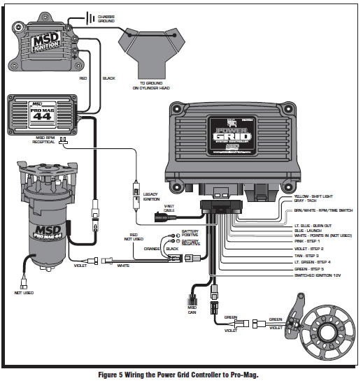
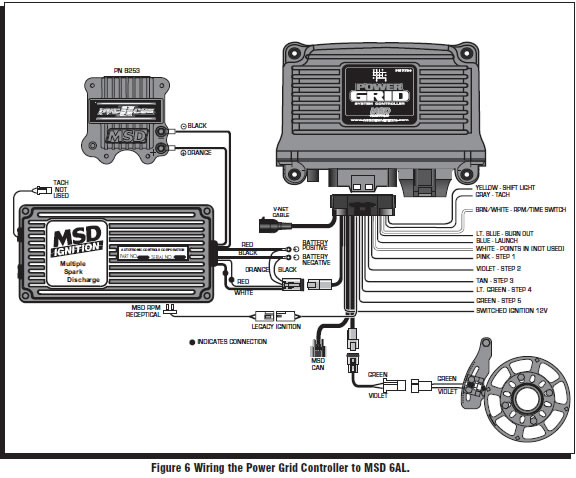
The Power Grid System Controller, PN 7730, is designed to be used with the Power Grid-7 Ignition Control, PN 7720. This is a high output CD ignition control. The Ignition System allows for the System Controller to be mounted on top of the Power Grid-7 to save space and provide a neat, compact installation. The System Controller can also be used with other MSD Ignitions such as the 7AL-2, MSD 8-Plus, and the Pro-Mag series. In order to use the rev limiting features of the System Controller the paired ignition must have a built-in Soft Touch Rev Control that uses plug-in RPM modules. Pages 10-12 show wiring diagrams for a variety of different ignition options.
MOUNTING
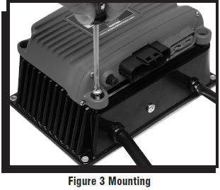
The Power Grid System Controller should be mounted in a sturdy, dry location that does not expose the unit to extreme heat. It is designed to be mounted on top of the PN 7720 Power Grid Ignition. Be sure to mount the Power Grid System Controller so the USB connector and Micro-SD card are accessible. The unit comes with thread-turning (aka. Selftapping) screws that will cut into the walls of the pre-drilled holes on the top corners of the Power Grid-7. If the Power Grid System Controller, PN 7730, is not being mounted on top of the Power Grid-7 the unit should be secured with the supplied hardware.
Note: Insecure or otherwise improper mounting of the unitcould result in damage or failure. Always make sure the unit is dry, avoids unnecessary excess vibration, and is not exposed to extreme heat.
MSD VIEW
The MSD View software controls all of the functionality of the Power Grid System Controller. The following information gives a brief explanation of each function or feature in the system as well as the settings that control it. While using the program, hover the mouse over a Function to display a brief explanation. When the system controller is connected to a PC via USB MSD View will automatically recognize it and load the settings stored in it. Note: Ensure that MSD View is installed on the PC prior to connecting the Power Grid Ignition Controller.
INSTALLATION OF THE VIEW SOFTWARE
1. Insert the installation CD Rom into the CD drive, wait up to 30 seconds, the CD will auto run, IF THIS DOES NOT OCCUR:
Locate and open the CD Drive.
Double click on the Setup file.
2. Select “Click here to Install Version X.XX”.
3. Once loaded, your monitor will have an MSD View X.XX logo. Accept the agreement. Drive the installation to your program files folder, press the enter key. The installation will complete, select OK.
4. A window will be opened with two aliases, double-click on the MSD View alias to launch the software.
5. Connect the system controller via USB. If the software does not recognize the controller and auto-connect, manually select the Power Grid in the popup window and click Connect.
Note: The View Software can be downloaded from www.msdignition.com.
SAVES AND TRANSFERS
Using the Power Grid System Controller changes are in real time if the computer is linked to the ignition. You can create and save numerous files on your PC and transfer them for testing purposes or to use for various locations and conditions.
The following instructions will go through a general description of the use of the Power Grid System Control following the tab system that you will see in the software.
PROGRAMMABLE FEATURES AND SETTINGS:
GENERAL
These are the most basic settings of the system. They will need to be set the first time the system is installed in a vehicle.
Number of Cylinders: This tells the system the number of cylinders. Must be selected correctly for proper timing and rev limiting.
Maximum Timing Reference: This is the advance that is set with a locked distributor or crank trigger. The system controller will use this as its base for all timing marks and can never advance past the preset point. It is critical that this advance is set properly.
Note: When using EFI the max timing reference and the main timing must be the same number.
Number of Gears: This tells the system the number of gears used in the transmission. This information can be used a variety of ways depending on the functions and modules used in the system.
Ignition Type: Found under General Settings, this option allows a user to select between using the Power Grid Ignition, PN 7720, or one of the MSD legacy ignitions.
DIAGNOSTIC LED INDICATOR
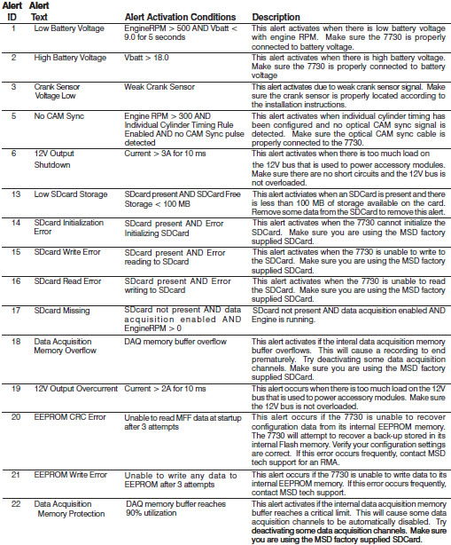
There is an LED that monitors the status of the system and allows the user to quickly know if all systems are working properly, recording is in process, or if there are errors. The possible conditions of the light are listed and explained below:
OFF – No power to the unit
1 Seconds ORANGE – Power ON light test
10 Seconds ORANGE – Slew/Time Rev Limiter Active (alert active for 60 minutes of power on after module is disconnected)
Blinking ORANGE – Recording in process
Blinking GREEN – Input trigger (Mag or Points) below 500 rpm without Alerts
Blinking RED – Input trigger (Mag or Points) below 500 rpm with Alerts
GREEN – Running with no active Alerts
RED – Running with active Alert
CAMSHAFT SYNCHRONIZATION
This is used only in applications where the individual cylinder timing is going to be used. The fiber optic connector communicates when the #1 cylinder fires. With this information, the controller knows which cylinder is being fired allowing for the individual cylinder timing capabilities. Only the MSD Fiber Optic Inductive Pickup Kit, PN 7555 will work for this system. Cam-sync’s cylinder #1 identification is also used in the data acquisition recordings.
GEAR SHIFT
In the Gear Shift selection the user can set items such as launch and shift delay so that the system will not have a false shift detected immediately after launch or a shift should there be an rpm drop for any other reason.
Launch Delay: The amount of time in seconds after the launch that the system will ignore an rpm drop to prevent false shift detection. This can be set from 0.00 to 10.00 in .01 second increments.
Shift Delay: The amount of time in seconds after sensing a shift that the system will ignore an rpm drop to prevent false shift detection. This can be set from 0.00 to 10.00 in .01 second increments.
1->2 Shift: By setting the rpm drop the user tells the system how to sense when the car is being shifted during a run. The setting is controlled by a drop down list with rpm from 200 – 1,500 or can be set to be activated by a Step Retard wire instead. The number of shifts that is shown is controlled by the number of gears the system is set to in the Settings – General tab.
SHIFT LIGHT
Using the Shift Light controls opens a variety of options designed to help make sure the light is exactly as desired. The shift light setting can be set by single rpm increments. In this control tab, each value can be entered to the exact rpm desired and the light’s intensity can be adjusted so that it is visible without blinding. The number of gears that appear on this tab will be auto-populated by the program after the number of gears is set in the general settings. This can also be used with a relay as a transmission shifter. The maximum current for this circuit is 3 amps.
Light Intensity: This percentage setting controls brightness of the shift light for easy use in both day and night racing. If being used for anything other than shift light control, the intensity must be 100%.
Power-On Test: Normally set to on but can be turned off if desired. The power-on test turns the shift light on as soon as the controller receives power to show that the circuit is complete and working.
Launch Light: The Shift Light will turn on if the engine rpm is between the launch low limit and the launch high limit. The light will blink if rpm is above the launch high limit.
Gear 1-5: A setting can be adjusted for each individual shift. To do this enter the engine RPM that should turn the Shift Light ON for each gear.
OUTPUT SWITCH
When the switch is activated it will supply ground to a circuit in order to turn an item on by time and/or rpm. The circuit can maintain up to 2 continuous amps. If more than 2 amps is needed a relay is recommended, PN 8961.
To activate or deactivate this circuit the system must see a programmed time and/or rpm setting which is programmed in the Settings – Output. Using both On and Off values will set a window to control the switch. The output will only be activated while within the set window and will be deactivated as soon as one or both sides of the windows are not met. All parameters must be met for the output switch to be activated. For example, if values are entered for both RPM On and Activation Point (timed on) then both of those values must be reached before the switch is activated. The rpm function becomes active and the time function begins counting after the Dark Blue launch wire is released.
Note: If using the time activation function a duration MUST be set above 0.00 or the switch will not be activated by time.
IGNITION TIMING
The user can set the timing from 0 - 60° BTDC. However, actual timing will never advance past the maximum timing reference nor will the timing retard more than 30° from the max timing reference. MAX and MIN timing lines will be displayed for convenient reference in the main engine timing tab. (Those lines can be turned off by unchecking them in the upper left column.)
Note: When using EFI the max timing reference and the main timing must be the same number.
Engine timing cannot exceed the maximum timing reference. In order to advance timing, the main timing map must be set below the maximum timing reference. I.E. If the crank trigger is at 40° and the main timing map is set to 35° there will be up to 5° of advance available.
ENGINE TIMING
Using MSD View software, an entire timing curve can be mapped. The map specifies the actual engine timing. The Power Grid will retard the input trigger to obtain the correct engine timing. The maximum timing reference must be set properly for correct engine timing. These maps include changes in 50 rpm increments and timing changes down to 0.1 degrees. A maximum of 30 points can be set per map.
This map will show all engine timing maps that are drawn based on rpm values such as timing curves per gear. The information for all of these maps is accumulative in the software. In order to edit a particular timing curve the user must go into the proper tab per function.
Start Retard: As part of the general engine timing curve, users can specify a start retard. While each engine responds differently, the typical recommendation for a start retard is to to pull out 10° from 0 - 600 rpm. A variety of other ideas can be applied to a start retard, including ramping timing in as engine rpm climbs. Use of such techniques is at the discretion of the user.
GEAR CURVES
This program provides the ability to modify the timing curve for each gear. One curve can be created for each gear, up to six, from 0 – 15,000 rpm in 0.1° increments for every 50 rpm. You can program up to 30 different points on each Gear Curve. The number of gears shown and how a shift is detected are dependent on the selected values in the Settings tab.
In the Ignition Timing – Gear Curves tab, an individual curve is plotted for each gear. Each change made for the gear curves references off of the Main Timing curve are set in the Engine RPM tab, not off of the max timing reference. Gear curves are NOT cumulative; i.e. Retarding 1° in 2nd gear does not affect 3rd gear settings.
Note: The gear curves are independent of each other. In order to make progressive changes, one gear’s starting point must match the final timing of the previous gear’s curve. Leaving a gear curve unedited will result in normal timing for that gear regardless of other gear curves ahead of or behind it.
INDIVIDUAL CYLINDER TIMING
Note: To control ICT an inductive pickup, PN 7555, is required.
To accomplish timing changes per cylinder the engine’s firing order must be entered first. Firing order is programmed in the tab Ignition Timing – Individual Cylinder – Firing Order by numbering the order into the Value column. Many common firing orders can also be imported from a database within the software; to do so simply go to FileImport and open the “firing_order” folder where an engine description can be selected.
Similarly, if an engine uses a firing order not included in these options the settings can be exported to be saved in the same file.
After the correct firing order is entered individual cylinder timing can be created by editing rules. Up to 10 rules can be entered to control various aspects of timing for a single cylinder at a time. Each rule has six (6) values that can be controlled; Cylinder, Retard/Advance, Timing, From Gear, Delay, and Ramp Time. To make a rule the first four control values must be entered, Delay and Ramp Time may be left at the default of 0 if desired. When timing is changed on an individual cylinder, in order to bring the cylinder back to original timing an equivalent amount of timing must be used to offset (DO NOT use 0°). I.E. If cylinder two is retarded by 3° in RULE 1, in order to put the timing back in the cylinder must be advanced in a later rule by 3°.
Cylinder: Double click this value to select the cylinder for which timing is to be altered.
Retard / Advance: Enter whether timing will be Retarded or Advanced. After using this option timing changes will always be entered as a positive number.
Note: Engine timing cannot exceed the maximum timing reference. In order to advance timing, the main timing map must be set below the maximum timing reference. I.E. If the crank trigger is at 40° the main timing map is set to 35° there will be up to 5° of advance available.
Timing Change: Enter the amount of timing that is to be retarded or advanced. This value will always be a positive number, regardless of whether advance or retard is desired.
From Gear: This setting determines from which gear the timing change will become active. If gear one is selected the timing change will be active at all times unless a delay is used.
Delay: This is the time, in seconds, that will pass prior to initiating the timing change after the proper gear change. This setting defaults to 0.0 but can be taken up to 5.0 seconds. If a timing change is desired during an entire run, but not other times the engine is running, this setting should be entered as 0.1 sec.
Ramp Time: The amount of time it takes for the Individual Cylinder Timing to be fully engaged. During this time the controller will ramp the timing change from the starting point to full timing.
Note: Changes made in Individual Cylinder Timing are cumulative. If a cylinder’s timing is to be altered for a duration of time two rules must be made, one to initiate the change and another to reverse the change at the appropriate time.
LAUNCH RETARD (TIMING BY TIME)
This function allows a user to set an engine timing curve based on the run time from launch (release of the dark blue wire). It can be programmed from 0° to 20° in 0.1° increments. Up to 30 trace points can be set per 0.01 sec. across the available 10 seconds. When the Launch wire is active, the retard value is the placement of the first dot. When 12 volts are removed from the Dark Blue wire the engine timing will follow the prescribed curve added to the base timing set at the engine RPM map.
STEP RETARDS
There are five step wires that control each of the corresponding step retards. These retards can be set so that they are not active until a specified rpm is reached even if the wire receives voltage. Using this system a step can activate as soon as the trigger wire receives 12 volts or after the engine reaches a specific rpm with 12 volts at the trigger wire. Once the retard is activated, timing can be changed in a single step or be ramped in over a period of time. The retard can also be turned off in a single step or ramp after a prescribed time after power is removed.

Note: These wires can also be used as Gear Select Indicators. See page 5.
Note: The Step-5 wire may be used as a Spool Rev Limiter. When using this wire for a retard and not a Spool Rev Limiter, the rev limit setting must be set above the max rev setting.
Activation through Wiring: Each step is activated by applying 12 volts to the corresponding wire. When multiple step retards are enabled at the same time the retard amounts are added together. The maximum retard allowed by the system is a total of 30° (including other retard amounts from a launch, boost, gear retard, etc).
Activation through RPM: Each step retard can also be activated through rpm. In order to achieve this, 12 volts must still be applied to the corresponding step retard, and an rpm must be entered in the respective step retard control. When 12 volts is applied, the retard will not activate until the rpm value is reached. Note that the retard will remain active until the rpm drops back below the set value. The step retard is added to all other retards in the system, including other active steps until it is deactivated.
Each of the five step retards has its own tab under the Ignition Timing – Step Retard tab. Within the individual tabs there are controls for the step retard.
Timing Retard: This is the amount of timing that will be retarded while this step is active. The timing can be adjusted in 0.01° increments.
Engine RPM: When this setting is used the engine must be above the prescribed RPM before the step retard will be activated.
On Ramp: The amount of time it takes for the step retard to retard the full amount. During this time the controller will ramp the timing retard from the starting point to full step retard.
Off Delay: This feature will set a time based delay to deactivate the step retards. The Off Delay is designed to keep the timing retarded after the wire is deactivated. This setting defaults to 0.0 sec but can be taken up to 5.0 sec by the user.
Off Ramp: The amount of time the system takes to turn the step retard off once power is removed from the step wire and any delay is complete. During this time the controller will ramp the step retard out.
Note: If you prefer to activate the step retards through the activation wires alone without considering rpm the setting for rpm should be left at the default of 0.
SHIFT RETARD
Using MSD View, a retard can be implemented momentarily to help maintain traction immediately after a shift. To do this, simply enter the amount of timing retard desired and the length of time the retard should be active for each shift. Whether using an rpm drop or a step retard activation wire for a trigger, as soon as the system detects a shift it will retard the timing for the prescribed amount of time.
REV LIMITER
A variety of different rev limits can be programmed per individual vehicle needs. The actual rev limiter will never exceed the maximum rev limiter.
Burnout Rev Limiter: This limit is activated when 12 volts are applied to the Light Blue wire. It is adjustable from 1,000 to 15,000 rpm. Note that the Slew Rev Limiter is disabled by the Burnout Limit.
Launch Rev Limit: This limit is activated when 12 volts are applied to the Dark Blue wire. It is adjustable from 1,000 to 15,000 rpm.
Latching: When this setting is enabled engine rpm must be below 7/8 of the launch limit setting while 12 volts is applied to the Dark Blue wire to engage the Launch Limiter. This allows clutch cars to wire the Dark Blue wire directly to the clutch switch without the need to use a relay. If Latching is disabled, the Launch Rev Limiter will be engaged anytime the Dark Blue wire receives 12 volts (such as during each shift) regardless of engine rpm.
Maximum Rev Limiter: This is the overrev limit to help protect the engine from damage.
Spool/Step 5 Rev Limiter: This program gives turbo cars a fourth rev limit to help the engine spool the turbo prior to the launch. It is active when 12 volts is applied to both the Light and Dark Blue wires at the same time or when using the Step 5 retard wire. (The Step 5 wire can allow for activating the Spool rev Limiter without activating the line-lock.) It is adjustable in 50 rpm increments from 1,000 to 15,000. Default is 12,000 rpm.
Safety Run Time Rev Limiter: Using two settings a safety limiter can be activated in case of incident. If for any reason the engine is still revving after the set amount of time since the launch limiter is released, this feature will lower the rev limit to a user specified rpm over 2 seconds. This will help anytime the throttle is open much longer than it should be, such as a stuck throttle linkage or an accident.
Users have two options to activate the Safety Run Time countdown; the Launch limiter, or the Safety RPM Start. In either case the Dark Blue wire must be activated so that time down can start upon its release. Many users will activate the Safety countdown by bringing the engine up on the limiter.
Users who do not wish to use the launch rev limiter can activate the safety run time countdown by taking the engine rpm equal or higher than the Safety RPM Start setting. This setting act only as a countdown activator and has no rev limiting ability.
DATA ACQUISITION
The data recorder on the Power Grid System Controller comes with a 2GB micro SD card which will easily hold more than an entire event’s worth of data. Within the settings for data acquisition on the system controller there are four tabs that provide options for when and what data is recorded. If a new micro-SD card is needed or wanted for any reason it is important to get a Class 6 or higher at the minimum, NOT all micro-SD cards will work. If there is question as to whether an SD card will work test recording should be done prior to a run.
The Power Grid System Controller will also easily send the data it records to compatible Racepak data acquisition systems. To connect the two systems simply plug the included VNet connector into an available space on the on the Racepak system. To be compatible the user must have a Racepak Data VNet Logger using DatLink Software v3.7.4 or higher. Default settings will send 13 channels of data to the RacePak system.
Settings:
This tab has two possible adjustments. The first setting allows a user to turn the data recording off, if desired. The second control tells the system what to do if the SD card is full. This setting allows the system to either stop recording or begin to write over data with the lowest recording name. By default the system is on and will overwrite once the memory is full.
Channels:
Each available data trace within the 7730 is listed in this tab. Each trace can be disabled individually in order to remove unneeded traces and generate smaller files. The Ignition In channel and the Ignition Out channel are high resolution and they generate the most amount of data at high engine rpm.
Start Recording:
The settings here tell the controller when to start recording data so that only useful information is stored. The recorder can be started by RPM alone or by adding a function to the RPM. For example, the default setting starts recording as soon as the Launch Rev wire is activated and the RPM is above 3,000.
Stop Recording:
In this tab the user controls when to stop recording. The recording can be stopped by reaching a lower rpm limit or a trigger such as a step wire signal. When stopping recording only one of these setting values must be triggered. There is also a setting to keep recording for some time after the trigger to ensure that all useful data is captured. Finally, there is a user set maximum recording time limit to ensure recording stops even if the system is not triggered for any reason.
ALERTS:
There are a variety of alerts that can arise in the Power Grid System Controller. If there are any errors or other causes of alert, the LED on the front of the controller will show red. Any time the red light shows the alerts should be checked so that errors can be corrected. By default, a pop-up box will appear as soon as an alert is registered. The pop-up window has a check box to disable the pop-ups if desired. The alerts window can also be opened manually two ways. On the bottom bar of the program window pane there is an alert counter that will show the number of alerts present. A single click on the alert counter at any time will open the alert window. The alert window can also be opened by going to the View menu on the task bar.