 FREE 1 to 3-Day Delivery on Orders $149+ Details
How To Install a Power Stop Z26 Street Warrior Brake Rotor & Pad Kit - Front & Rear on 2005-2010 GT

Shop Parts in this Guide
Front Brake Pad Installation Guide
The installation guide is for reference only. Please refer to the vehicle’s service manual or professional installer for complete instructions.
Ninety percent of the brake pad changes you make during the life of your vehicle will be to the front brakes because they do 60% to 70% of the braking. On most cars, you can look through the openings on the outside of the wheel/rim assembly to see the pads. On some vehicles, you may have to remove the wheel to see the pads. Look at it from above or the side. The pad will be pressed against the shiny metal rotor. The best way to inspect a pad is through visual inspection. If the pad depth is less than 3/16 inch, plan on replacing it soon. If it’s less than 1/8 inch, you should change the brakes immediately.
You can also tell if the brakes should be replaced if you hear noise from the wear sensor on the pad. However, some parts do not have wear sensor clips, i.e. noisemaking clips that are mounted on the brake pad to tell you when the pads need to be changed. If you hear a screeching sound when you apply the brakes, then you are due for a brake change. (If the sound is more like a metal rasp or grinding sound, then you’ve already damaged your rotors and need to fix the brakes immediately.)
STEP ONE:
Have the following parts available before you start the brake change: 1) Power Stop brake pads such as the Evolution ceramic pads, 2) Power Stop cross-drilled or slotted rotors, 3) a bottle of DOT 3 or 4 brake fluid as recommended by your owner’s manual, 4) brake pad grease 5) a c-clamp. You should also have a car jack and jack stands.
STEP TWO:
Block the rear wheels so the car won’t roll once you jack it up. Put the car in park and set the parking brake firmly.
STEP THREE:
Before jacking the car up off the ground, loosen the lug nuts on the wheels just enough to break them free. Work them off just enough until they loosen their resistance and become easy to turn with the tire iron. Raise the car and support with safe jack stands under flat spots on the frame. Usually the frame support area is immediately to the rear of the front wheels.
CAUTION:
Always use jack stands. Never attempt to work on an elevated vehicle held in place only by a hydraulic jack.
STEP FOUR:
Remove the lug nuts and the wheel. It is best to work on one wheel at a time, leaving the other side intact as a point of reference. As a safety precaution, roll the wheel/tire assembly under the front-center of the car, between the jack stands, and set it down beneath the engine’s K-member. In the event of a faulty jack stand.
STEP FIVE:
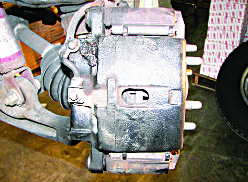
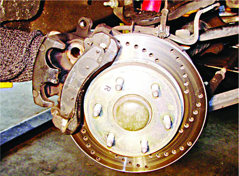
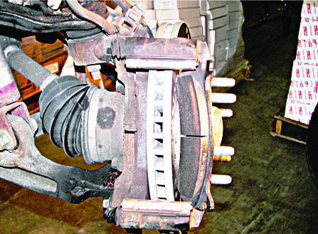
Review the brake components. A disc brake assembly is composed of . a caliper, two brake pads, and a rotor. The caliper works on pressurized brake fluid through a piston in the caliper. The caliper has a fixed part bolted to the spindle knuckle and a slide part that holds the brake pads. The caliper is mounted with two bolts. These bolts usually have dust boots. When the brakes are applied, the caliper piston squeezes the pads against the rotor creating friction.
Fig. 1
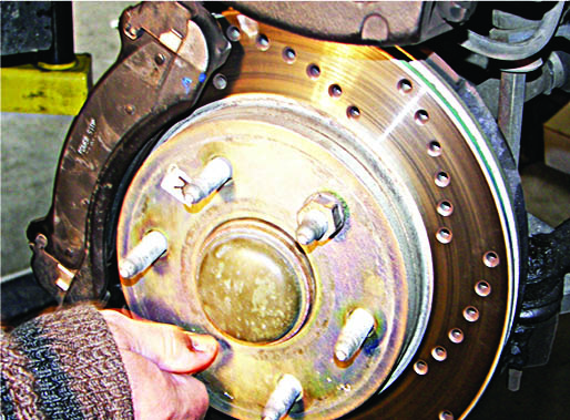
NOTE:
If you are not replacing or turning down the rotor, then install 2 lug nuts backwards to hold the rotor in place when removing the caliper (fig. 2).
Fig. 2
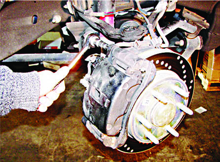
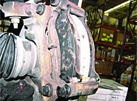
STEP SIX:
Remove the two bolts that hold the two parts of the caliper together (fig 3). Gently slide it out and away from the rotor. Hang the caliper inside the wheel well using a coat hanger, so that the hose is not stressed. Do not let the caliper dangle from the brake hose line. Inspect the inside of the caliper and remove the brake pads. Remove the two remaining bolts that hold the caliper slide to the knuckle. Use a wire brush to clean rust from the rails where the pad contacts the caliper.
Fig. 3
STEP SEVEN:
With the caliper out of the way, remove the rotor. Sometimes the rotor rust will make it bind and you will need to use a mallet to loosen it. Tap both the front and back side alternating left and right, top and bottom of the rotor. The rotor thickness should be measured and compared to the minimum discard thickness that is etched on the rotor. If the thickness is less than this minimum, then the rotor should be replaced.
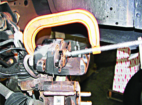
STEP EIGHT:
The next step is to move the piston back inside the caliper. The piston has extended as the pad material wears. With new thicker pads, you must return the piston back inside the caliper body to give the thicker pads room for installation. First crack open the bleeder screw on the caliper to allow brake fluid to be relieved. Place a container under the caliper to collect the fluid. Get a large C-clamp, place the used brake pad over the face of the piston to protect the surface from marring, and work it back that way. As you turn the handle on the clamp, it will increase pressure on the piston, until it becomes flush with the surrounding metal. Brake fluid will be released through the bleeder. Then loosen and remove the C-clamp. Close the bleeder screw for now. If you cannot open the bleeder screw, then push the C-clamp in slowly to prevent unsafe back pressure and damage to the ABS modulator, brake valving or master cylinder. It may be necessary to drain some fluid from the master cylinder reservoir.
Fig. 4
NOTE:
many rear brakes pistons cannot be retracted with a C-clamp as they screw in and out. This type of rear brake piston will have two recessed notches where you can use a set of needle nose pliers to retract the piston.
Fig. 5
STEP NINE:
Check and replace all hardware as needed. Improper hardware can lead to noise or poor brake pad performance. Clean the caliper rails or hardware sldes where the pads make contact. Clean the hub mating surface with a wire brush. Rust or debris on the hub can cause rotor runout and lead to wheel vibration.
STEP TEN:
Resurface the rotor or replace the rotor. Most auto retailer stores provide rotor resurfacing. After machining, use a 120 grit sandpaper on the rotor in a light circular motion to give a non-directional finish. Clean the rotor with mild soap and wipe clean with a lint-free cloth. Do not use petroleum based cleaners.
Fig. 6
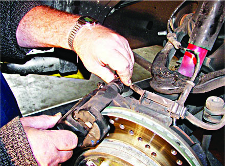
STEP ELEVEN:
Install the new rotor and remount the caliper bracket (not the piston part) to the spindle knuckle arm. Use brake grease to lubricate the edge of the brake pad plate where it touches the caliper. Do not put grease on the friction material. The lubricant goes between the plate and the piston or caliper back. Don’t overlook this. If you don’t do it, you may get brake noise when you apply the brakes.
Fig. 7
NOTE:
When you install new rotors, it is recommended that you check rotor runout. Rotor runout can cause brake pulsation. First tighten the stud nuts to the manufacturer specification using spacers as required. Mount a dial indicator and rotate the rotor while measuring the runout. Runout should be less than /-.001 inch. If runout exceeds this then mark the high spot, remove the rotor and index it two studs and check to see if the high spot moved. Make sure that the hub and rotor mounting surface is clean.
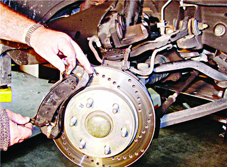
STEP TWELVE:
With the fixed part of the caliper bolted to the spindle. Reinstall the brake pads in the caliper slide, and make sure that they are pressed back to leave clearance for the rotor to slide between them. Slide the caliper over the rotor and line up the bolt holes. Bolt the piston part of the caliper to the caliper bracket. Note:sometimes the rubber boot will extend the bolt and cause interference during installation. Just push the rubber boot back to allow the caliper to slide over the rotor.
Fig. 8
STEP THIRTEEN:
Bleed the brakes to remove air from the brake line. First make sure the brake fluid is full to the top. Have a buddy press down slowly on the pedal as you monitor the bleeder screw. When you see a constant stream of fluid, close the bleeder screw. It usually takes three pumps of the pedal to clear the air out of the line. Check the master cylinder reservoir and replace brake fluid to the MAX line. Do not overfill the reservoir. Pump the brakes several times to seat the brake pads to the rotor and check the reservoir one more time.
Fig. 9
STEP FOURTEEN:
Replace the wheel and bolts. Drop the car to the ground to finish tightening the bolts to the manufacturer’s specified bolt torque. Alternate tightening sequence by going to the opposite side of the hub. A torque gun is not recommended.
IMPORTANT:
BREAK IN NEW FRICTION USING THE PAD BEDDING PROCEDURE AS FOLLOWS. PROPER PAD BEDDING CAN PREVENT ROTOR WARPING.
The break in procedure is critical! If you do not break in the pad properly, it can result in brake pedal pulsation and thermal shock to the rotor causing stress cracks. Break in the pads as follows: 5 moderate to aggressive stops at 40 mph to 5 mph without letting the brakes cool and do not come to a complete stop. Then do 5 moderate stops at 25 mph to 5 mph and let the rotors cool after each brake application. You should expect to smell some resin as the brakes get hot.
For the first 100 miles, avoid towing or hauling loads while the pad completes the resin cure.

