 FREE 1 to 3-Day Delivery on Orders $149+ Details
How to install a Steeda Bumpsteer Kit on your 2005-2012 Mustang
Installation Time
1 days
Tools Required
- Adjustable Wrench
- Ratchet
- 18mm socket or wrench
- 7/8 inch socket or wrench
- Channel locks or vice grips
- Shop rag
- Penetrating oil
- Hammer or mallet
- Jack stands
- Floor jack
- Lug nut wrench
- Impact wrench (optional)
- Tie-rod end separator (optional)
Installation
- Having a lift to get the car up in the air makes it a little easier, but it is perfectly do-able in a home garage as long as a good set of jack stands and a good floor jack are used.
- Make sure the exhaust and brake components are cool enough before starting work near them.
- Using the method described in this guide, it is possible to set the alignment (toe in/out) close to original; however it is highly recommended that you get the alignment checked after performing the installation to ensure even tire wear and proper handling characteristics.
- Ignore the fact that the brakes were removed on the car in this guide. It has brake cooling ducts and the flange for the duct on the special dust shield was in the way of installation. The stock dust shield and brake assembly do not need to be removed.
Removal & Installation:
1. Begin by jacking up the front of the car and make sure it is safely supported on jack stands. Remove the front wheels.
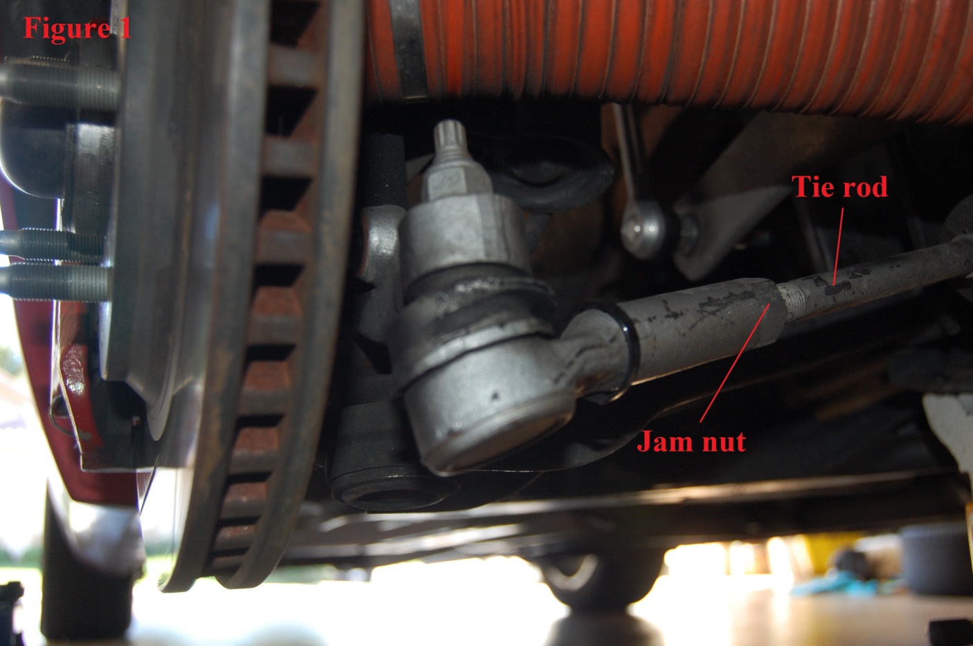
2. The first step in disassembly of the old tie-rod ends is to back off the jam nut on the tie-rod. Hold the tie-rod itself with vise-grips or pliers while backing off the nut just far enough so it is not contacting the rod-end anymore. (Figure 1)
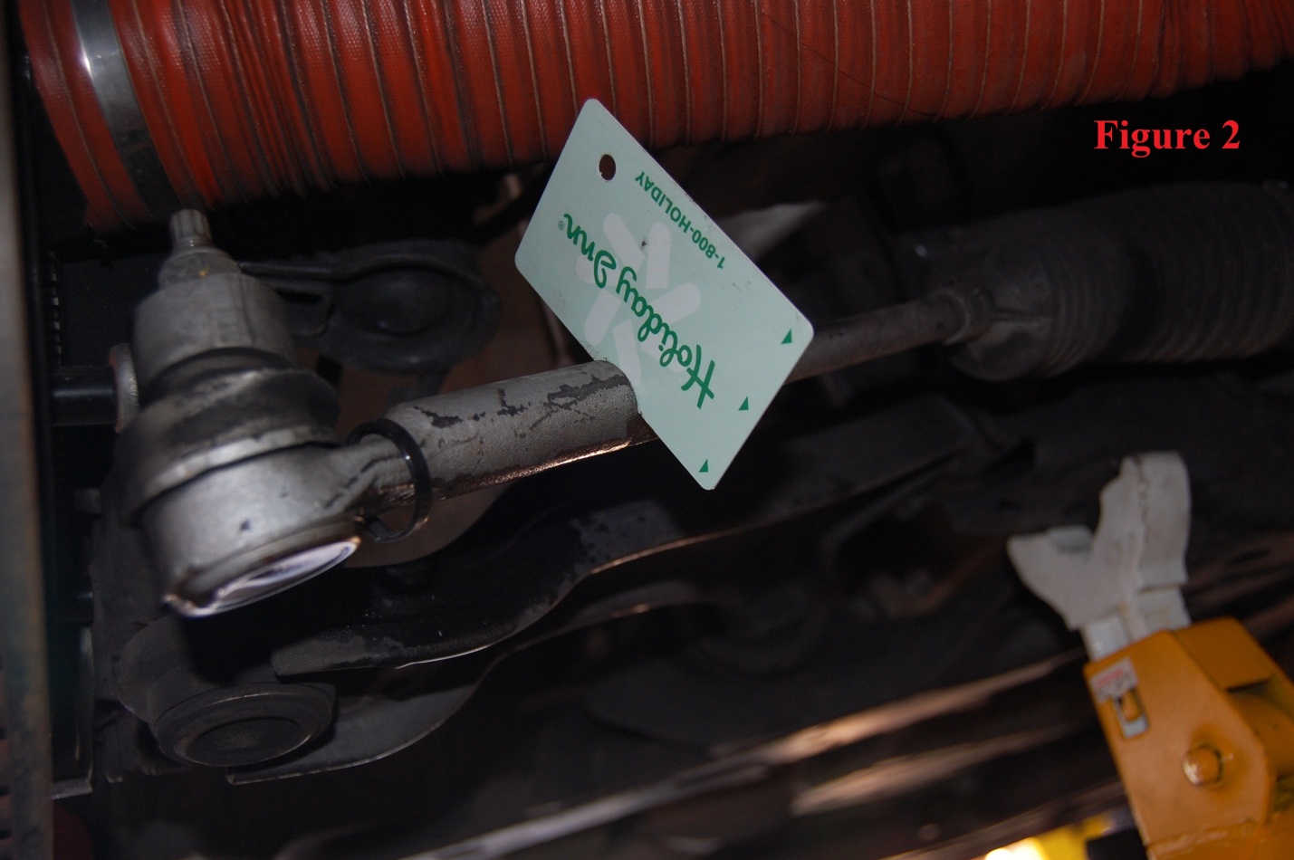
3. Slide a credit card or similar spacer between the jam nut and the rod-end. (Figure 2) Lightly sandwich it between the two by tightening the jam nut slightly. The purpose of this is to set a point to which the new rod-end will install up to.
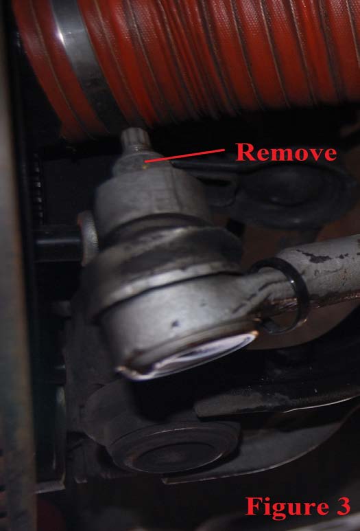
4. Next, remove the nut that holds the rod-end into the spindle. (Figure 3)
5. With the nut removed, the rod-end can be separated from the spindle. A tie-rod end separator is useful here, but it can also be removed with a hammer. Spray penetrating oil onto the bolt where it protrudes through the spindle. Then, strike the side of the spindle with a hammer to loosen the bolt, then straight down onto the bolt. It might take a few raps of the hammer on the top of the bolt, but it will eventually pop right out.
6. After the bolt pops out, the tie-rod end is ready to be removed. Simply unscrew the rod-end off of the tie rod.
7. Take the blue aluminum collar and thread it onto the tie rod. Screw it on until it is close to the jam nut that’s still on the tie rod. Now, take the card used earlier and sandwich it between the jam nut and blue collar. Once lightly sandwiched, remove the card and tighten the jam nut down against the collar.
8. Next, take the steel spherical end and thread it into the blue collar.
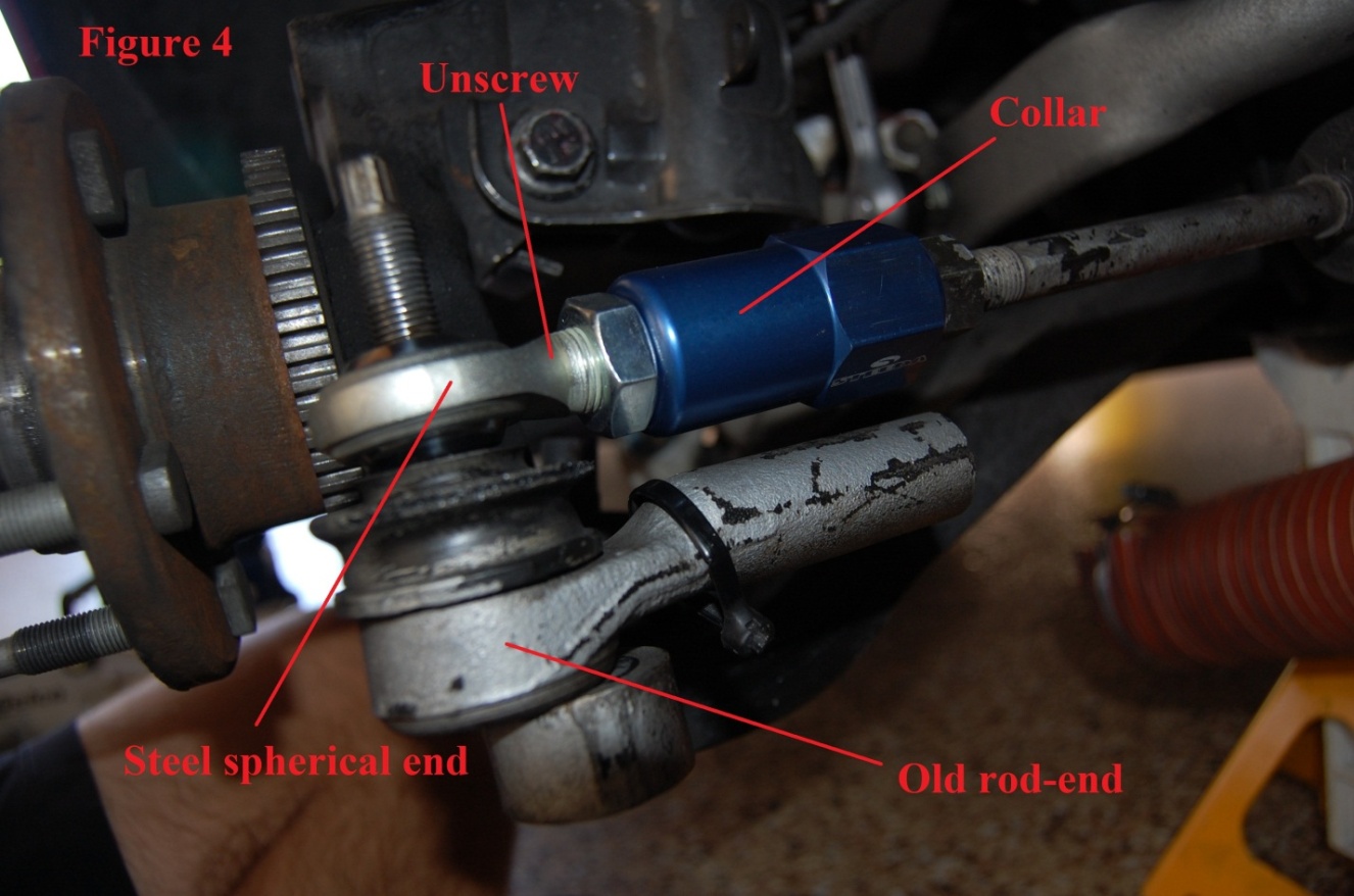
9. Using the old rod-end, match the length of the new assembly to that of the old one by inserting the old rod-end bolt through the new steel end. Then unscrew the steel end until the length of the whole new assembly (blue collar and steel spherical end) matches the length of the old tie-rod end. Finally, tighten the jam nut on the steel end against the collar. (Figure 4)
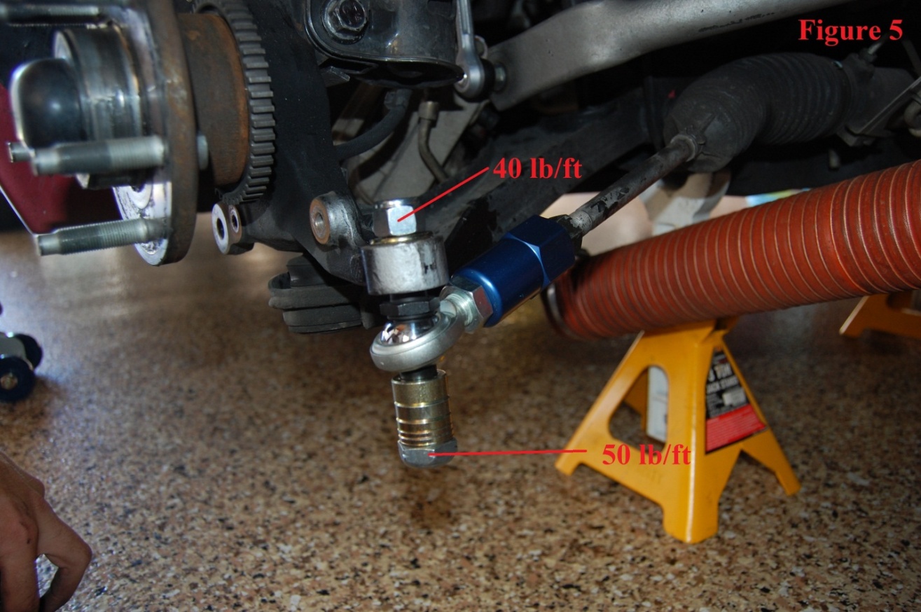
10. Discard the old tie-rod end. Take the new black stud and insert the tapered portion through the spindle. Use the supplied washer and 18mm nut and torque to 40 lb/ft. (Figure 5)
11. Arrange the spacers above the spherical rod-end if on a lowered car, or below the rod-end if on a stock height car as pictured. The number of spacers and where they are needed will depend on if/how much the car is lowered. The goal is to keep the tie-rod parallel to the lower control arm. With this in mind, arrange the spacers as necessary. With all the spacers on, tighten the bottom 7/8 inch nut to 50 lb/ft. (Figure 5)
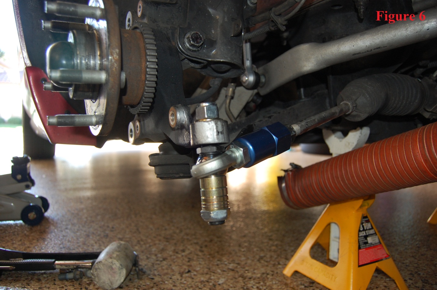
12. Finished install. (Figure 6)
13. Put the wheels back on and have the alignment checked to ensure proper tread wear and handling.
Installation Instructions written by AmericanMuscle customer Andrew Kozak 10.24.11
Related Guides
-
Installation
-
Installation
-
Installation

