 FREE 1 to 3-Day Delivery on Orders $149+ Details
How to install a Wilwood Superlite Front Brake Kit on your Mustang

Shop Parts in this Guide
Installation
Important Notice - Read This First
Before any tear-down or disassembly begins, review the following information:
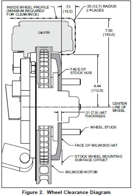
- Review the wheel clearance diagram (figure 2, page 3) to verify that there is adequate clearance with the wheels you will be using with the installation.
- Front brake kits do not include flex lines. OEM brake lines will not adapt to Wilwood calipers. Check the assembly instructions, or associated components section for brake line recommendations before assembly. In addition, Wilwood offers an extensive listing of brake lines and fittings on our web site: www.wilwood.com.
- Due to OEM production differences and other variations from vehicle to vehicle, the fastener hardware and other components in this kit may not be suitable for a specific application or vehicle.
- It is the responsibility of the purchaser and installer of this kit to verify suitability / fitment of all components and ensure all fasteners and hardware achieve complete and proper engagement. Improper or inadequate engagement can lead to component failure.
General Information and Disassembly Instructions
Installation of this kit should ONLY be performed by persons experienced in the installation and proper operation of disc brake systems. Before assembling the Wilwood front disc brake kit, double check the following items to ensure a trouble-free installation.
- Make sure this is the correct kit to match the exact make and model year of the vehicles spindle (i.e., brakes for a 1990 Mustang spindle will not fit a 2005 Mustang spindle).
- verify the factory hub stud pattern matches the brake hat in this kit.
- Verify your wheel clearance using Figure 2.
- Inspect the package contents against the parts list to ensure that all components and hardware are included.
Disassembly
- Disassemble the original equipment front brakes:
Raise the front wheels off the ground and support the front suspension according to the vehicle manufacturer’s instructions. Remove the wheel. Remove the two bolts from the backside of the spindle that hold the stock caliper mounting bracket and lift off the bracket and stock caliper as one unit. If space is a problem, you may have to unbolt the stock caliper from the caliper bracket before removal. Then slide off the stock hat and rotor assembly. Optional: Removal of the dust face plate to facilitate easy removal of additional parts and/or for aesthetic purposes if you will be running spoked wheel and would like to see the drilled/slotted rotor.
- Clean and de-grease the spindles as well as the stock caliper bracket bolts.
Remove all nicks or burrs on the spindle snout and threads.
Assembly Instructions
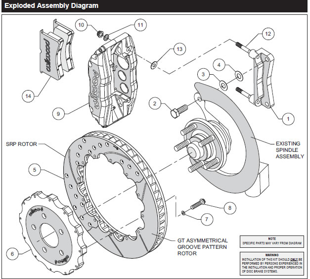
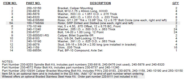
Assembly Instructions (numbers in parenthesis refer to the part list (above) and diagram on the preceding page):
- The caliper mounting bracket assembly (1) should be installed first with clean, dry threads on the mounting bolts. The bracket must tighten squarely against the outboard side of the caliper mount bosses on the spindle body. Inspect for interference from casting irregularities, maching ridges, burrs, etc. Slide bolt (2) through the hole in the spindle body where the OEM bolt was removed. Use one thin shim (4) between the bracket and spindle during initial trial fitting. Later, after the caliper, pad and rotor alignment have been checked, and any necessary shims have been put in place, the mount bolts (2) should be coated with red Loctite® 271 and torqued to 47 ft-lb.
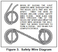
- With the larger I.D. side of the rotor (5) facing away from the hat (6), bolt rotor (5) to hat (6) through the backside of the rotor using washers (7) and bolts (8). Torque bolts (8) to 85 in-lb. Safety wire bolts (8) using standard 0.032 inch diameter stainless steel safety wire as shown in Figure 3. Please refer to Wilwood’s data sheet DS-386 (available at www.wilwood.com/Pdf/DataSheets/ds386.pdf) for complete safety wire installation instructions. Slide the rotor/hat assembly onto the spindle. Install a couple of lug nuts (hand tighten) to keep the rotor/hat assembly in place while continuing with the installation.
- With the bleed screws pointing up, mount the caliper (9) onto the caliper bracket (1) with the self locking hex nut (10), flat washer (11), through the top of the caliper and mounting stud (12) with .035” thick shim (13) positioned between caliper (9) and caliper mounting bracket (1). Finger tighten. Check to see that the top of the rotor is aligned with the top of the brake pad. If adjustment is necessary, add or substract flat washers (13). View the rotor (5) through the top opening of the caliper (9). The rotor (5) should be aligned in the center of the caliper (9). If not, adjust the caliper (9) by adding or substracting shims (4) and/or (3) placed between the spindle assembly and the caliper mounting bracket (1). Finger tighten and recheck alignment. Lubricate caliper mounting studs and nuts with lightweight oil, reinstall the caliper, torque the caliper nuts (10) to 30-35 ft-lb.
- remove the bridge bolt from the caliper (9) and install the disc brake pads (14). Reinstall the caliper bridge bolt.
- Remove the two lug nuts that were used to hold the rotor/hat assembly in place during caliper installation.
- NOTE: OEM rubber brake hoses generally cannot be adapted to Wilwood calipers. The caliper inlet fitting is a 1/8-27 NPT. The preferred method is to use steel adapter fittings at the caliper, either straight, 45 or 90 degree and enough steel braided line to allow for full suspension travel and turning radius, lock to lock. Carefully route lines to prevent contact with moving suspension, brake or wheel components. Wilwood hose kits are designed for use in many different vehicle applications and it is the installer's responsibility to properly route and ensure adequate clearance and retention for brake hose components. Wilwood offers a hose kit, P/N 220-9111, which includes hoses, fittings, etc., all in one package for this application. This optional flex line kit also includes a new flex line bracket. You will need to remove the OEM bracket (retain OEM hardware) and replace with the new bracket utilizing the OEM hardware.
Specified brake hose kits may not work with all Years, Makes and Models of vehicle that this brake kit is applicable to, due to possible OEM manufacturing changes during a production vehicle's life. It is the installer's responsibility to ensure that all fittings and hoses are the correct size and length, to ensure proper sealing and that they will not be subject to crimping, strain and abrasion from vibration or interference with suspension components, brake rotor or wheel.
In absence of specific instructions for brake line routing, the installer must use his best professional judgment on correct routing and retention of lines to ensure safe operation. Test vehicle brake system per the 'minimum test' procedure stated within this document before driving. After road testing, inspect for leaks and interference. Initially after install and testing, perform frequent checks of the vehicle brake system and lines before driving, to confirm that there is no undue wear or interference not apparent from the initial test. Afterwards, perform periodic inspections for function, leaks and wear in a interval relative to the usage of vehicle.
Bleed the brake system. Reference the general information and recommendations on page 5 as necessary for proper bleeding instructions.
Install the wheel and lug nuts, torque to OEM specifications.
Repeat the procedure for the other wheel.
Additional Information and Recommendations
- Please read the following concerning balancing the brake bias on 4 wheel disc vehicles. This Mustang kit can be operated using the stock OEM master cylinder. However, as with most suspension and tire modifications (from OEM specifications), changing the brakes may alter the front to rear brake bias. Rear brakes should not lock up before the front. Brake system evaluation and tests should be performed by persons experienced in the installation and proper operation of brake systems. Evaluation and tests should be performed under controlled conditions. Start by making several stops from low speeds then gradually work up to higher speeds. Always utilize safety restraint systems while operating vehicle.
- For optimum performance, fill and bleed the new system with Wilwood Hi-Temp° 570 grade fluid or EXP 600 Plus. For severe braking or sustained high heat operation, use Wilwood EXP 600 Plus Racing Brake Fluid. Used fluid must be completely flushed from the system to prevent contamination. NOTE: Silicone DOT 5 brake fluid is NOT recommended for racing or performance driving.
- To properly bleed the brake system, begin with the caliper farthest from the master cylinder. Bleed the outboard bleed screw first, then the inboard. Repeat the procedure until all calipers in the system are bled, ending with the caliper closest to the master cylinder. NOTE: When using a new master cylinder, it is important to bench bleed the master cylinder first.
- Test the brake pedal. It should be firm, not spongy and stop at least 1 inch from the floor under heavy load. If the brake pedal is spongy, bleed the system again. If the brake pedal is initially firm, but then sinks to the floor, check the system for fluid leaks. Correct the leaks (if applicable) and then bleed the system again.
If the brake pedal goes to the floor and continued bleeding of the system does not correct the problem, a master cylinder with increased capacity (larger bore diameter) may be required. Wilwood offers various lightweight master cylinders with large fluid displacement capacities.
- NOTE: With the installation of after market disc brakes, the wheel track may change depending on the application. Check your wheel offset before final assembly.
- If after following the instructions, you still have difficulty in assembling or bleeding your Wilwood disc brakes, consult your local chassis builder, or retailer where the kit was purchased for further assistance.
Brake Testing and Pad Bedding
- Make sure pedal is firm: Hold firm pressure on pedal for several minutes, it should remain in position without sinking. If pedal sinks toward floor, check system for fluid leaks. DO NOT drive vehicle if pedal does not stay firm or can be pushed to the floor with normal pressure.
- At very low speed (2-5 mph) apply brakes hard several times while turning steering from full left to full right, repeat several times. Remove the wheels and check that components are not touching, rubbing, or leaking.
- Carefully examine all brake components, brake lines, and fittings for leaks and interference.
- Make sure there is no interference with wheels or suspension components.
- Drive vehicle at low speed (15-20 mph) making moderate and hard stops. Brakes should feel normal and positive. Again check for leaks and interference.
- Always test vehicle in a safe place where there is no danger to (or from) other people or vehicles.
- Always wear seat belts and make use of all safety equipment.
