 FREE 1 to 3-Day Delivery on Orders $149+ Details
How to Install BBK Headers & X-Pipes on Your 2011-2012 Mustang V6
Installation Time
1 days
Tools Required
- 5/16" Wrench
- 3/16 socket with small ratchet
- 1-1/2" extender
- 1/2" wrench
- 5/8" wrench
- 7/8" wrench
- 3/4" wrench
- 15mm wrench
- Soldering kit, heat shrink & wire tubing
- 16 gauge wire & 16 gauge wire stripper
- Zip ties
- Jack stands, jack and ramps;Car lift if applicable (recommended for smoother, quicker install)
- Light source for under the car & in theengine bay
- Towels to protect the side of your car
- Safety Glasses

Shop Parts in this Guide
Installation
Time Required:Approximately 9 hours w/ 3 installers (highly recommended having help during install); process will be much faster with a lift and/or power tools.
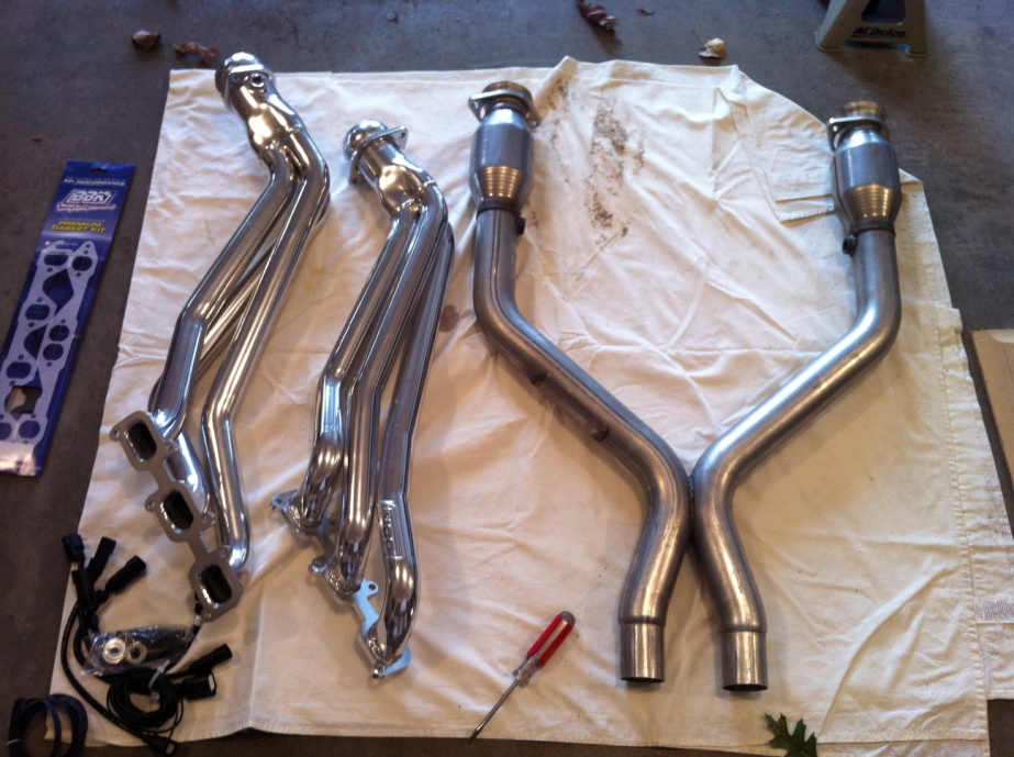
Supplied components; Long Tubes & Shorty X-pipe sold separately (shown in the picture above):
- Long tube headers
- Shorty X-pipe
- Header gaskets
- O2 sensor extensions
- Packet of 4 screws, 4 washers and 4 nuts
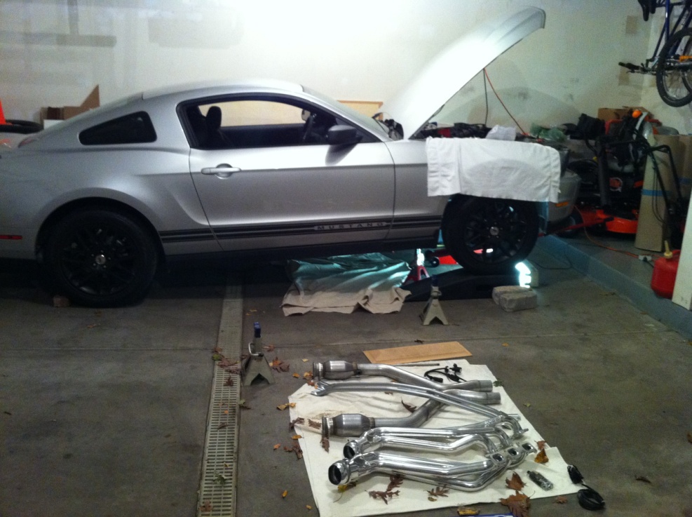

This picture shows where the jack stands and jack should be placed. It is recommended to leave jack in extended position with jack stands for added safety.
Instructions for lifting car up (as seen in picture above):
1. Drive car on to ramps; using flat pieces of wood snug at each ramp base will prevent bumper shroud from scraping ramps.
2. Now place jack in the middle, under engine bay and raise it. There will be rigid part of the frame in the middle where the lift point is.
3. Lift car up so the tires are about 3” off the ramps and slide the jack stands under the shown left and right side of the sub frame. Cardboard will work well to protect frame from being scratched from jack and jack stands.
4. Make sure jack stands are aligned and placed directly under sub frame; check the stands to be sure they are ready for use.
5. Clear area and VERY slowly turn release valve handle so car will lower slowly onto jack stands.
6. Leave jack pressed on the frame for added safety during installation and check jack stands for even and safe alignment on each side of sub frame.
Removal of stock manifold and mid-pipe assembly:
1. First, disconnect the negative battery cable. If you have a strut tower bar, you will need to remove that next (it will be in the way during later steps).
2. Next, remove the (2) aluminum heat shields on each stock header manifold with a 5/16” wrench. (Picture below shows them already removed)
3. With a 5/8” wrench, unscrew the (2) screws on each manifold to down-pipe connection. The top screw on this side can be seen to the left of the steering column. This part is difficult due to the hard to reach area and the little room allowed for turning of the wrench.
4. Now, take off the (12) total nuts (6 on each side) with a 1/2” wrench and store in a safe place.
Note: Some nuts will come off with their screws, separate these when removed from engine block.
5. Remove the (12) total screws (6 on each side) with a small 3/16 socket and ratchet; store these in a safe place as well.
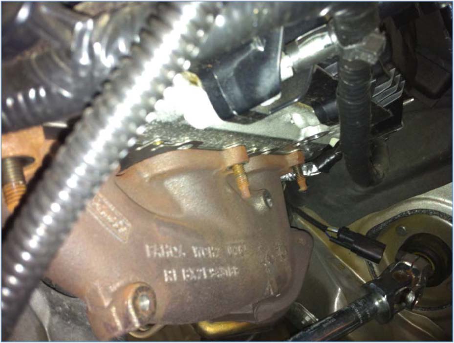
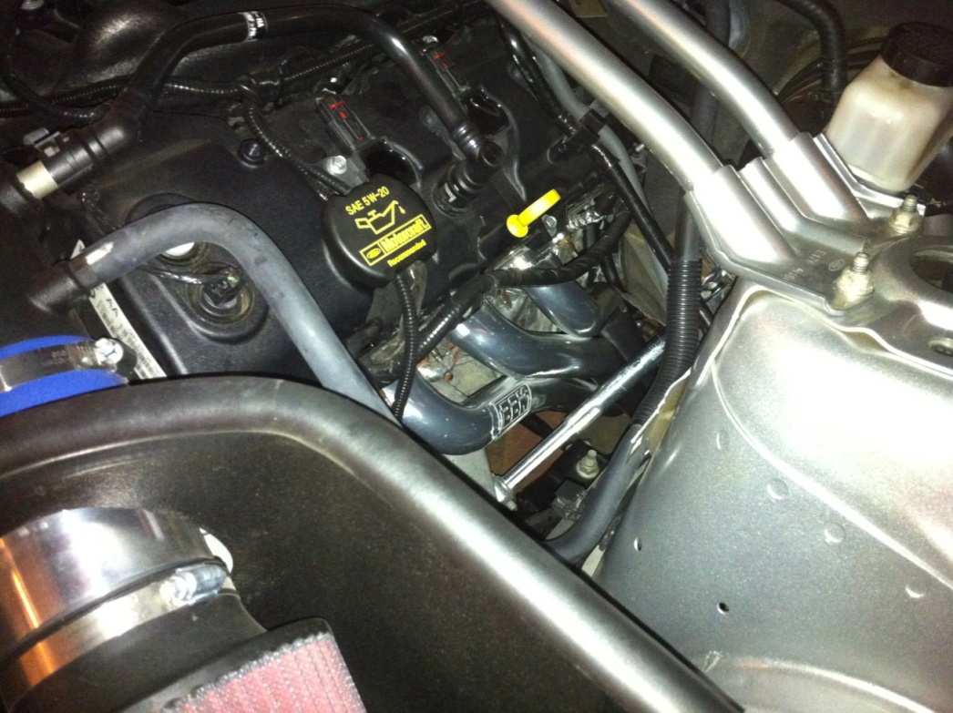
6. You can see behind the manifold in the picture above (red circle) the unplugged O2 sensor plug. This one leads to the down-pipe and is connected to the catalytic converter. You can disconnect these now by pressing on the tab at the connection and pulling out. The connections are located snug behind the engine (driver & passenger side).
7. Once the manifold screws and manifold to down-pipe connection screws are removed, the manifold can be taken out along with the stock metal gaskets on each side.
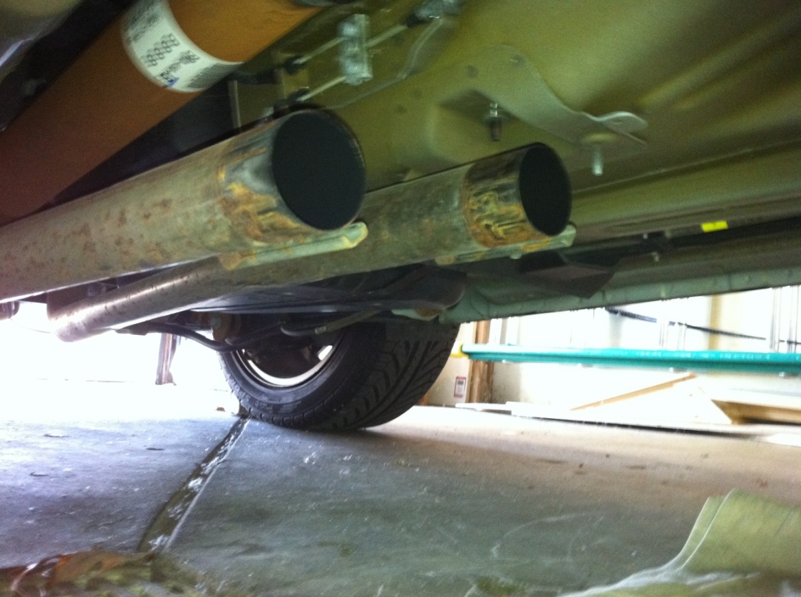
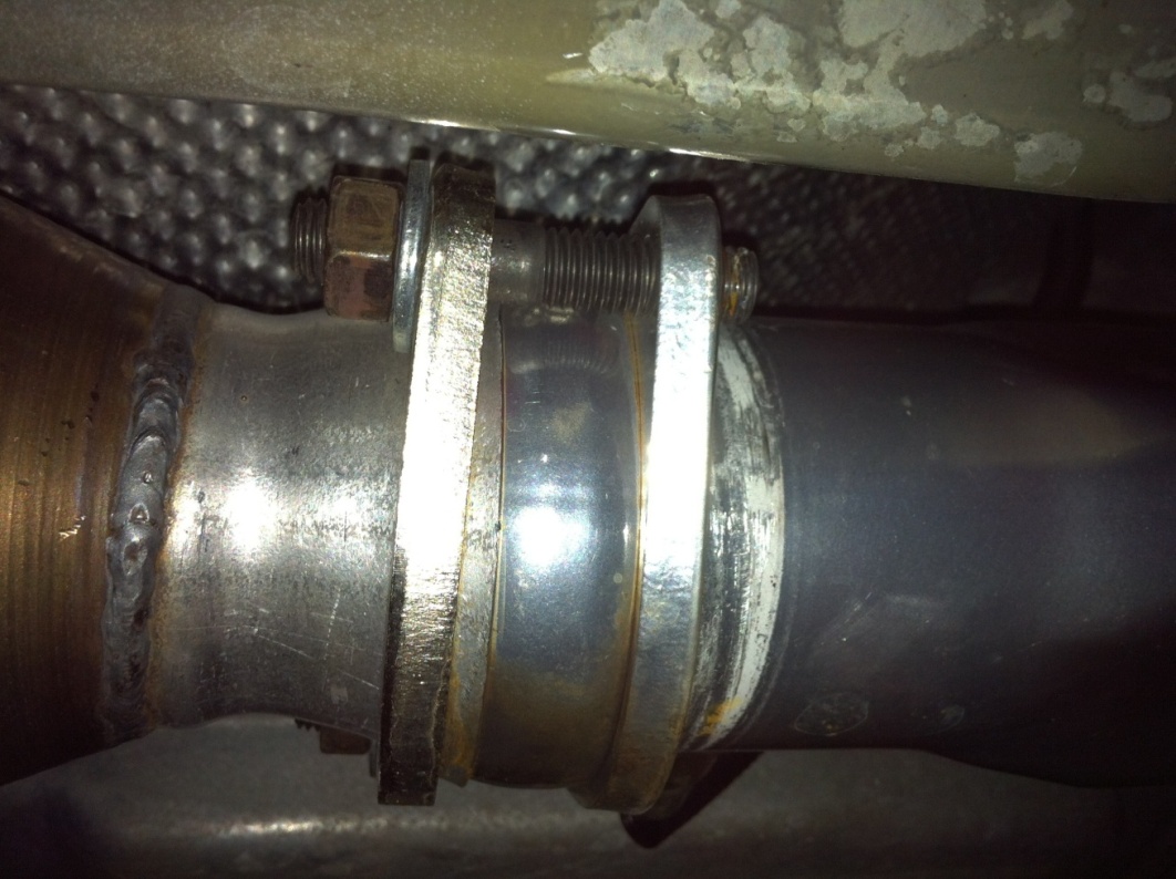
8. You are now ready to remove the stock mid-pipe assembly underneath the car that is being held on by clamps. These are located in the middle and underneath the driveshaft. Use a 15mm closed loop wrench to loosen the (4) total nuts (2 on each clamp).
9. Set aside the clamps to be reused. Clamps and stock mid-pipe assembly are removed in picture below.
10. Unplug the rear set of O2 sensors (driver and passenger side) by pressing on the tab and pulling them out. These are a bit hidden right alongside the transmission.
11. Slide out stock mid-pipe from underneath car carefully. Note: Have at least one person guiding the top part of assembly from the engine bay to slide down and out while another person underneath is pulling assembly out.
12. Lastly, remove all (4) O2 sensors. Use a 7/8” wrench to unscrew them from the mid-pipe assembly. Label each sensor with tape listing which sensor is which (front driver/passenger; rear driver/passenger).
Installation of new BBK Long Tube Headers & Shorty X-pipe:
1. Reinstall the (12) total manifold screws (6 on each side) using the 3/16 socket and ratchet and slide in the new supplied header gaskets. Note: Be sure the gaskets match the screw pattern on the new header for each side.
2. Slide the BBK Long Tube Header up from underneath the car on the driver side and screw the (6) nuts onto the manifold screws and tighten; repeat this for the passenger side. Finished attachment is shown in the picture below.
3. Slide the cat-‐ back clamps on (they will fit only one way) and screw the (4) supplied screws into the header connection rings on the bottom of the long tube headers. In this installation, the short thread of the screw is on the x-pipe side shown in the picture below.
4. Slide the x-pipe in the loosened cat-‐ back clamps first and then align with the opening of the long tube header. The screws on the header rings will slide into the x-pipe rings; add the (4) supplied washers/nuts and tighten. Note: During this installation, the x-pipe and cat-back piping were not pushed up all the way and were not flush with the chassis when first installed. Be sure this whole assembly is pushed up enough and held there while tightening.
5. Tighten the (2) cat-‐ back/x-pipe clamps with a 15mm wrench. Tighten the (4) nuts with a 3/4” wrench at the header rings (as shown above).
6. The whole assembly is now complete; now just the O2 sensors need to be extended and installed.
Instructions for extending and installing the O2 sensors:
1. The front O2 sensors will need extending. BBK has supplied extensions that will work only for the rear O2 sensors. Start with one of them (front passenger or front driver). Their wires will need to be cut in a specific way as shown in the diagram below.
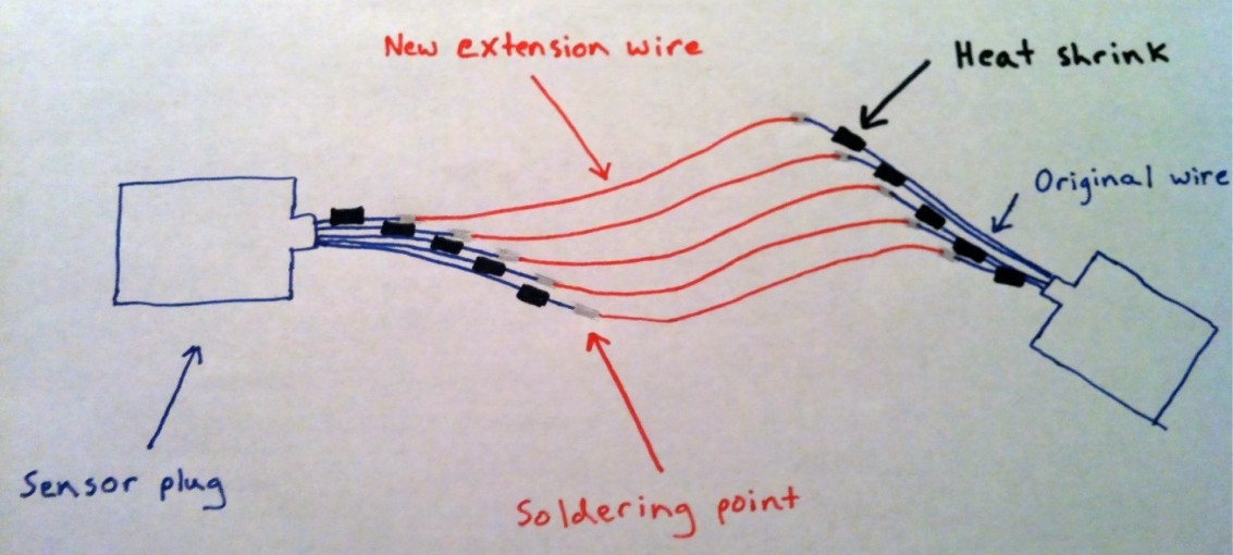
2. Cut the original wires, shown as blue in diagram. This is done so if any heat shrink were to ever wear off, there would be no contact of exposed wires. Use a wire stripper to strip and expose about 1/4" of wire on each new wire end. Cut heat shrink tube into (10) 1/2” long tubes.
3. Now cut (5) new strands of 16-‐ gauge wire, each 18” long. Strip and expose about 1/4” for all wire ends.
4. Mesh each new wire (shown as red) to each original wire (shown as blue) on both sides.
5. For this whole sensor, there will be (10) soldering points; they are shown in grey on the diagram.
MAKE SURE THE HEAT SHRINK TUBES ARE ON ALL WIRES BEOFRE SOLDERING.
6. Solder each point and then slide the heat shrink tubes over for each newly made connection. Shrink them by using the heat of the soldering utensil.
7. Slide on protective wire tubing, spanning the whole length of the newly extended O2 sensor.
8. Repeat steps 2-7 for the other O2 sensor.
Instructions for O2 sensor installation:
1. Start by screwing in each sensor probe in the bottom part of the long tube headers with the 7/8” wrench and tighten.
2. Reconnect the now extended O2 sensor with the sensor plug behind engine; do this for both sides. Note: make sure to loop around driver side wire around gear selector arm (auto trans) so there is no contact or rubbing.
3. Zip-tie each extended wire to a near-‐ by wire to keep them secured.
4. Repeat steps 1-3 for the rear O2 sensors; these connections are up along transmission.
5. Finally, reconnect the negative battery cable.
6. Installation is now fully complete!
7. To get car back on the ground, pump jack up so chassis is a few inches off jack stands. Remove jack stands and make sure top of car ramps are aligned with both front tires. Clear area and lower jack by slowly turning the release valve handle until car is fully resting on ramps.
8. Be sure to check that all sensors are connected, all bolts and nuts are tightened and that all connections are solid before starting up.
Please note:
- When first running, the exhaust will be smoking from the grit inside the tubing from manufacturing. This is normal and smells a bit, but this will wear off very soon.
- Drive it around for a few miles and make sure there are no unusual sounds and/or responses from the engine.
- Setup will sound a little noisier at first and will take a few hundred miles to break in for a nice deep, raspy growl.
- A good 20 horsepower is added with this system with stock mufflers.
- Even more power can be added with a custom written tune (highly recommended) and also with free-‐ flowing axle-‐ back mufflers.
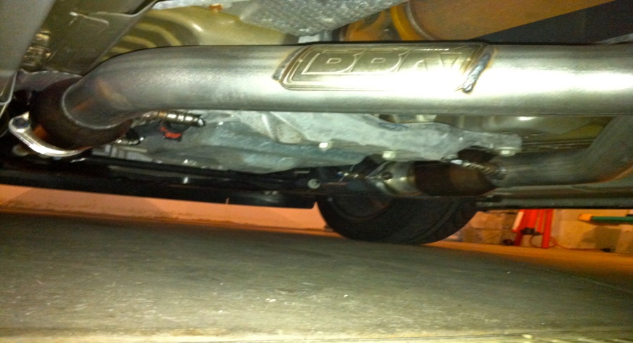
Below are a few pictures of the new set-‐ up after a few hundred miles of use:
Installation Instructions written by AmericanMuscle customer Andrew Kuhrmeyer 11.10.11
Related Guides
-
Installation
-
Installation
-
Installation

