FREE 1 to 3-Day Delivery on Orders $149+ Details
How to Install a Mustang Rear Valance on your 2015-2016 Mustang
Installation Time
2 hours
Tools Required
- Ratchet
- 7 mm Metric Socket
- 8 mm Metric Socket
- 10 mm Metric Socket
- Air Saw
- 1/8" Drill Bit
- 3/16" Drill Bit
- 1/4" Drill Bit
- Torque Wrench
- Cutting Tool
- Safety Glasses
- Masking Tape
- Drill
- Center Punch
- T20 Torx Bit
- T25 Torx Bit
- Scissors
- Marker

Shop Parts in this Guide
Section A- Removal
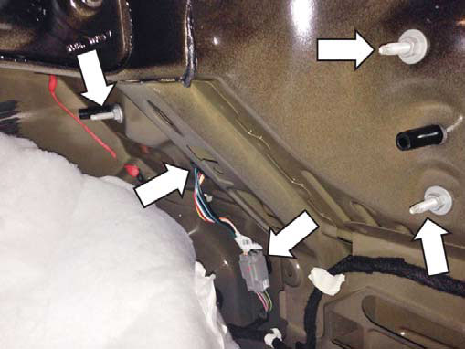
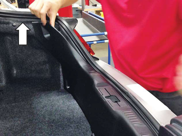
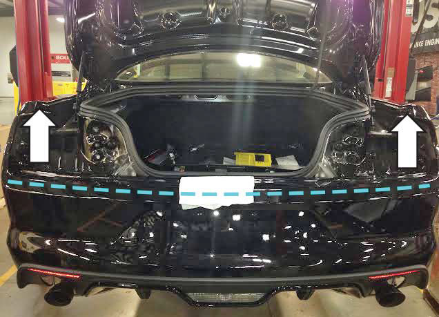
The following section will guide you through the removal of the factory bumper cover. 1. Open the trunk and remove the two (2) plastic nuts and push-in retainer on each side of the vehicle. Remove the rear trunk trim panel by pushing each end forward to disengage it from the studs and then lift the panel up to release the remaining clips.


2. Remove the three (3) nuts that retain each tail lamp with a 10 mm socket and disconnect the electrical connectors for each tail lamp. Push the wiring harness grommets through the body and remove the LH and RH tail lamps.
3. Remove three (3) push-in retainers in the back of both rear wheel wells.
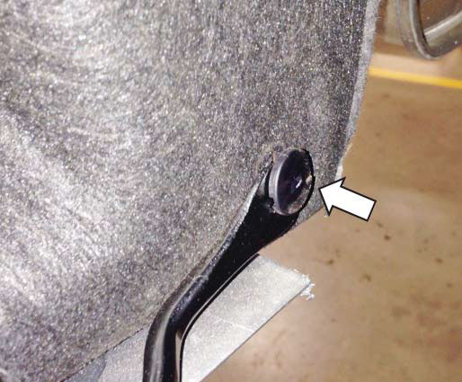
4. Pull the inner rear fender covering back to reveal the three (3) screws and remove them with a 7 mm socket.
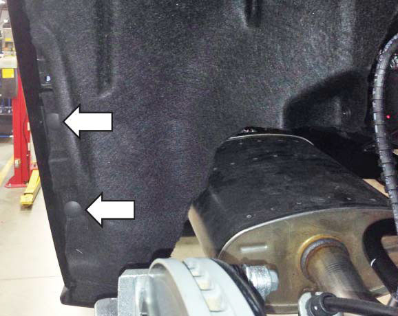
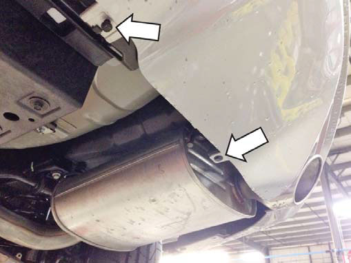
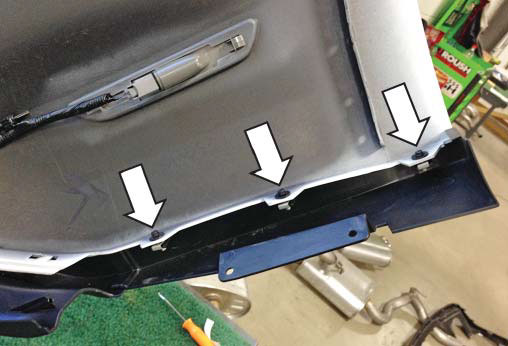
5. Remove two (2) push-in retainers under each side of the rear bumper behind the rear tires.
6. Remove two (2) 7 mm screws and two (2) push-in retainers on the LH and RH sides under the rear bumper.
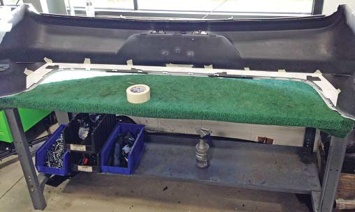
To protect the bottom of the bumper cover from damage, place on a protective surface once removed.
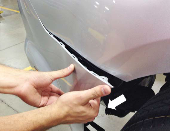
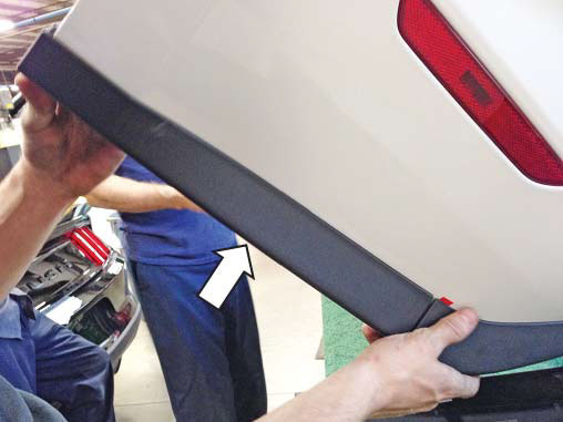
7. Pull outward on the LH and RH sides of the bumper cover near the rear tires to release it from the side retaining clips.
8. Pull up and rearward along the top edge of the bumper cover to release the upper retaining clips.
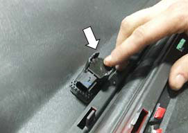
9. Locate and release one (1) retaining tab on each side of the bumper cover near the outer edge of the tail lamp mounting area.
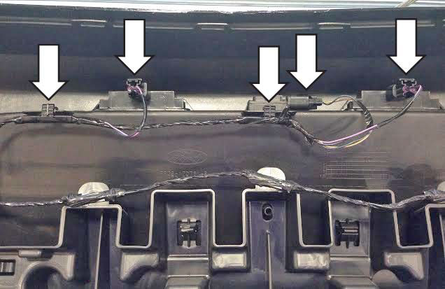
10. Hold the center of the bumper cover and partially remove it in order to gain access to remove the wiring harness connector under the RH tail lamp. With the connector removed, remove the bumper cover and place it on a protective surface.
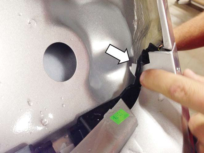
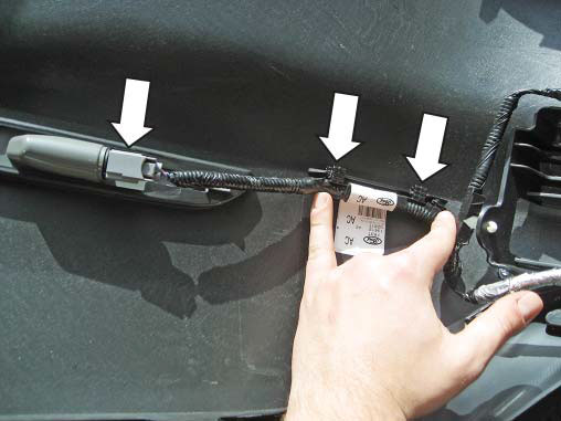
11. Disconnect the side marker electrical connectors as well as the edge clips that retain the wiring harness on each side of the bumper cover.
12. Disconnect the license plate light and trunk release electrical connectors as well as the two (2) edge clips that retain the wiring harness.
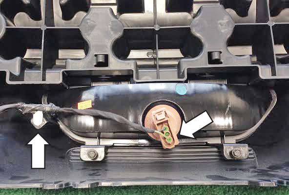
13. Disconnect the reverse light electrical connector as well as the push pin that retains the wiring harness.
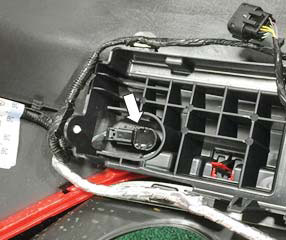
NOTE: Only follow this step if your vehicle is equipped with backup sensors. 14. Disconnect the backup sensors connectors on each side of the rear bumper cover.
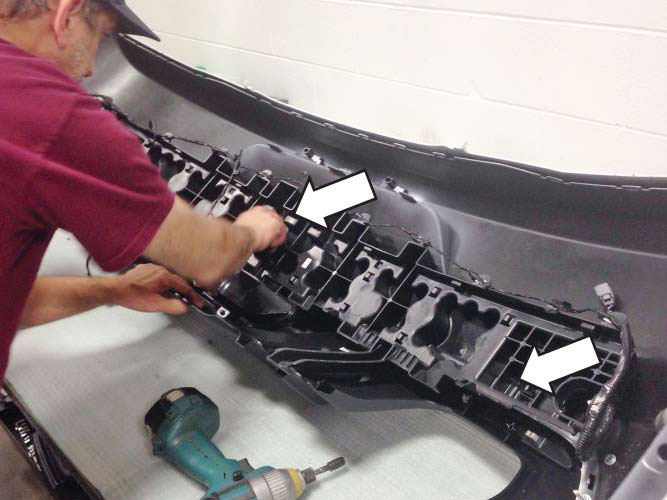
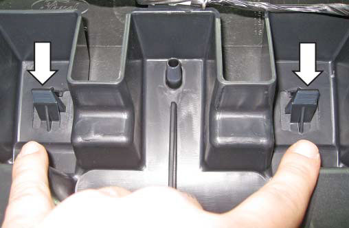
15. Remove the center bumper cover reinforcement piece by releasing the four (4) retaining tabs.
NOTE: Only follow this step if your vehicle is equipped with backup sensors.
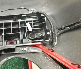
16. Disconnect the remaining backup sensor connectors with the center bumper cover reinforcement piece lifted out of the way
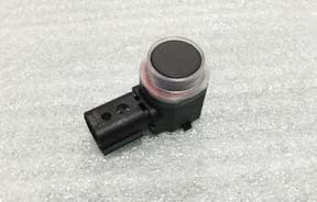
17. Remove the four (4) factory back up sensors by releasing the retaining tabs and then set them in a safe place. Remove the four (4) plastic factory back up sensor brackets from the bumper cover with a suitable cutting tool. Use caution to not damage the factory bumper cover.
18. Remove the two (2) rear refl ectors by removing each nut with a 10 mm socket and then releasing the retaining tab.
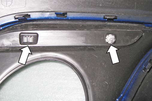
19. Remove the four (4) 7 mm screws for the reverse light.
20. Remove three (3) 7 mm screws and three (3) J-clips for the factory rear valance trim piece from each side of the rear bumper cover.
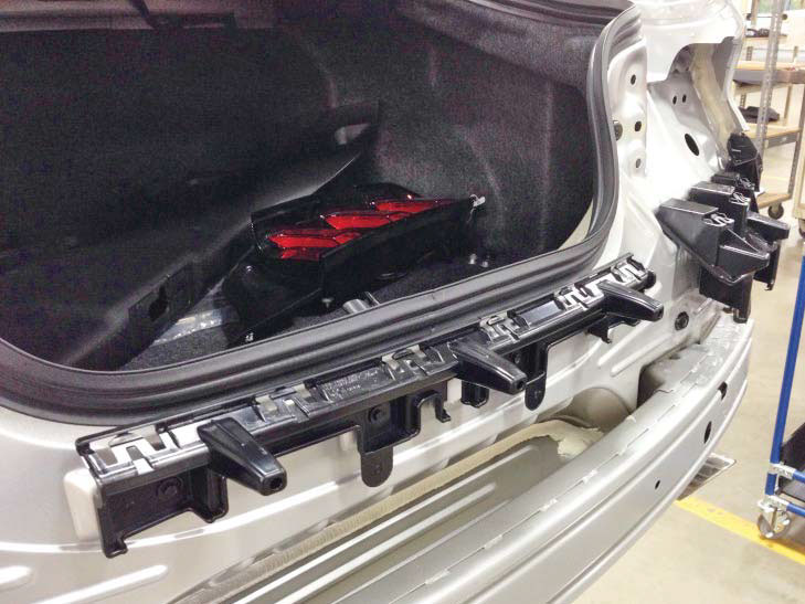
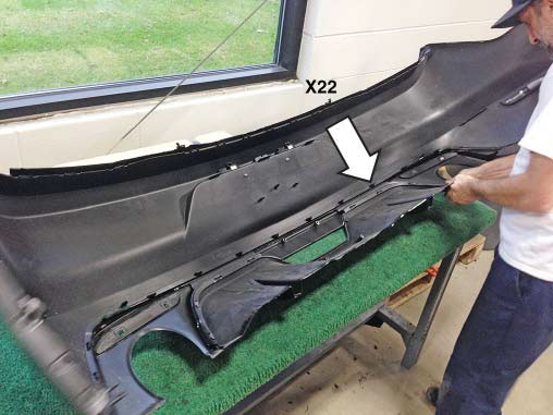
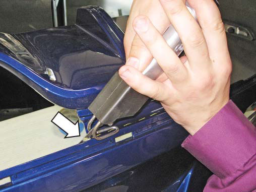
21. Remove the lower bumper cover trim piece by releasing the twenty-two (22) retaining tabs.
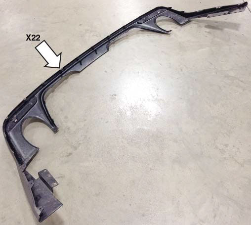
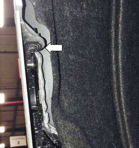
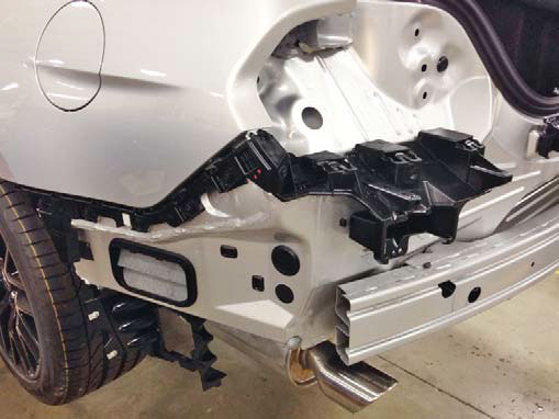
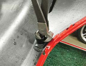
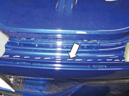
22. Using an air saw, cut and remove the factory lower valance as shown below.
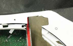
23. Cut out the drill template provided for the rear valance panel and tape into position. NOTE: The bottom edge of the template must be fl ush with the surface edge of the bumper cover and the two (2) middle alignment tabs should be centered on the two (2) middle slots as shown below.
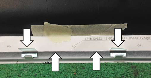
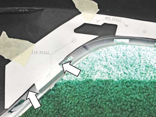
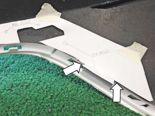
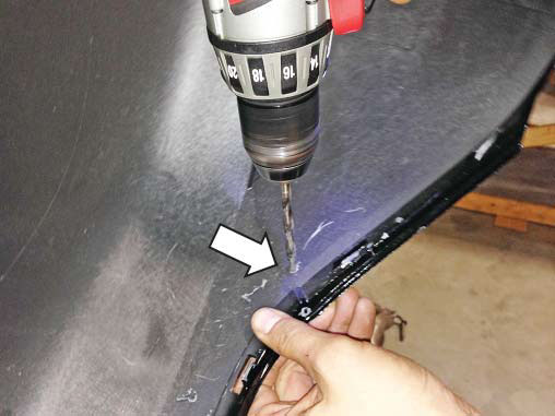
24. Using a 1/8" drill bit, drill fi fteen (15) pilot holes and then follow up with the appropriate drill bit as indicated on the template. NOTE: Trim the outlined windows in the template ONLY if your vehicle is equipped with reverse sensors.
NOTE: Only follow this step if your vehicle is equipped with backup sensors.
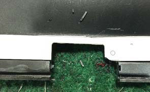
25. With the outlined windows in the template as a guide use a suitable cutting tool and cut out the windows as shown below.
NOTE: Only follow this step if your vehicle is equipped with backup sensors.
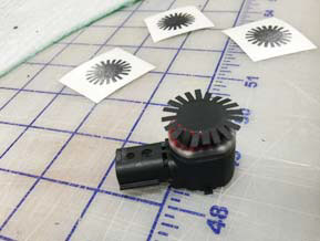
26. Remove the silicone caps on each factory back up sensor, install the color match vinyl (P/N: 1315-BUSVINYL) to each sensor and then replace the silicone caps as shown below.
27. Using alcohol, clean the rear valance and bumper cover mating surfaces.
28. Install the 2-sided tape (P/N: TAPE-015- 12.5X1385) on the back side of the rear valance (P/N: 1315-17F954).
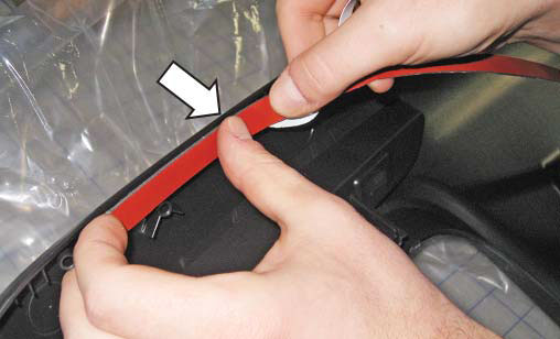
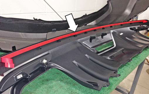
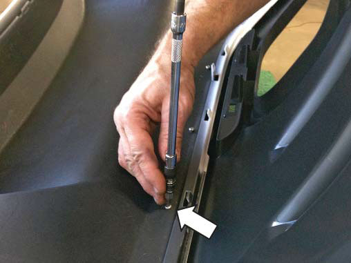
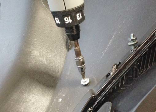
29. Peel a small portion of the backing off the doublesided tape on each end in order to create "fl ags" that will allow for complete removal once the valance is secured into position. Install two (2) studs (P/N: 90207A253) into the outer middle bosses on each side of the rear valance and to the correct depth as shown.
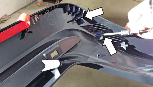
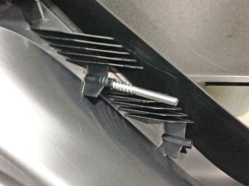
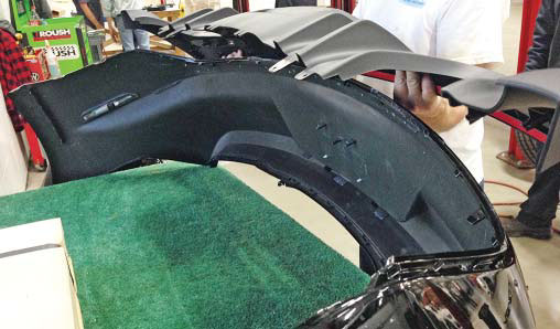
30. Place the rear valance on the bumper cover by fi rst aligning the two outer studs with the lower outer holes drilled in step 21. Loosely install one washer (P/N: 1133153) and one nut (P/N: 90480A011) onto each stud and then lay the back of the rear bumper cover down onto a protective surface
31. Loosely install eleven (11) screws (P/N: 99397A767) into the top row of holes. Loosely install two (2) screws (P/N: 90925A245) with two (2) washers (P/N: 1133153) into the top outer corners while being sure to properly align each hole with the plastic bosses on the valance.
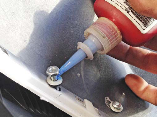
32. Remove the backing off the 2-sided tape, apply blue Loctite® to the threads on the studs that were installed in step 24 and then torque all of the fasteners that were installed in steps 24-26 to 0.7-0.8 Nm.
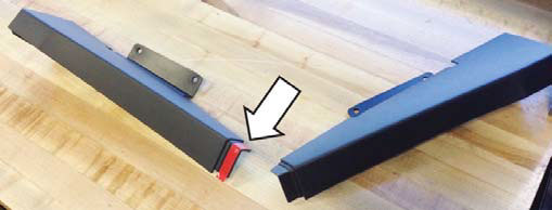
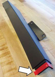
33. Apply 3M Ad-Pro® (P/N: 021200-27571) onto the rear edges of the side valance pieces (P/N: 1315-17F955 & 1315-17F956) and then install the 2-sided tape (P/N: TAPE-015-12.5x68).
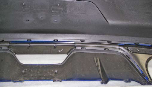
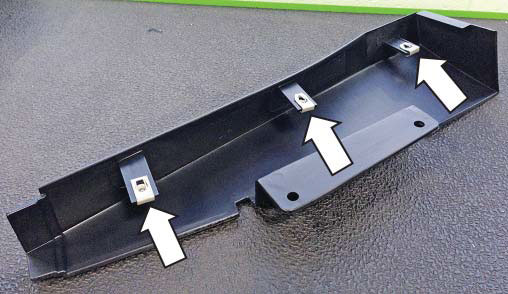
34. Install three (3) J-clips that were removed in step 17 onto the side valance pieces as shown in next image and create a removal tab with a portion of the 2-sided tape backing.
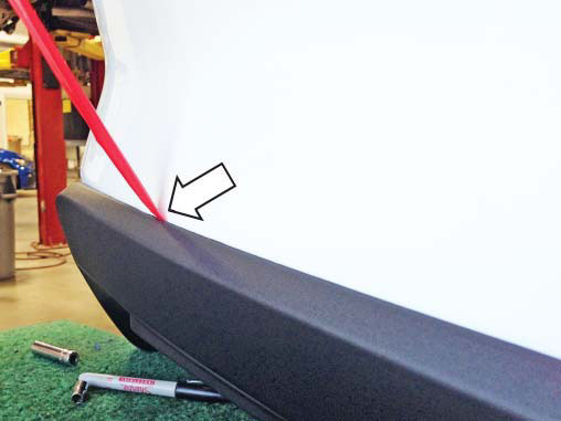
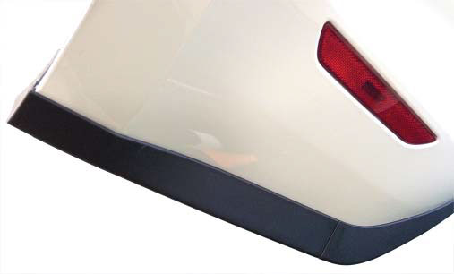
35. Install the side valance pieces onto the rear bumper cover using three (3) screws that were removed in step 17 and completely remove the backing from the 2-sided tape. With the side valance pieces installed press fi rmly along the back edges to ensure that the 2-sided tape has bonded adequately.
36. Reinstall the rear refl ectors, reverse light and the bumper cover reinforcement piece that were previously removed by reversing steps 14-16. Reinstall the side marker, license plate light, trunk release and reverse light electrical connections that were previously removed by reversing steps 11-13. If equipped reinstall the factory back up sensors into the new brackets that are on the ROUSH rear valance (P/N: 1315-17F954BUS).
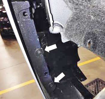
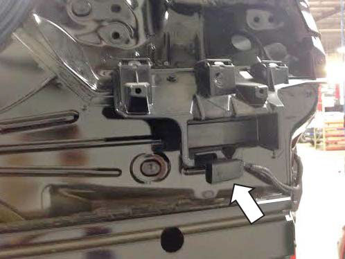
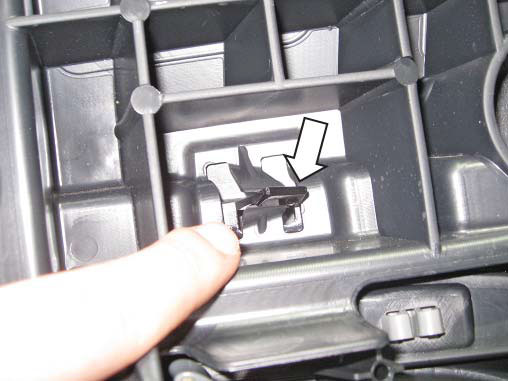
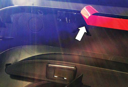
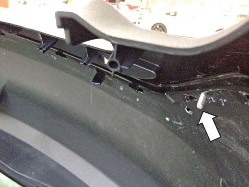
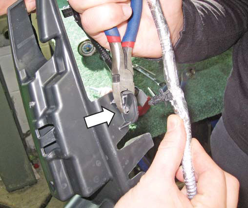
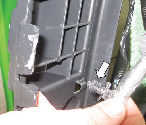
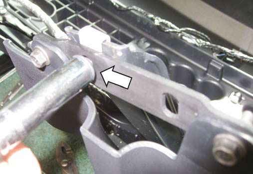
37. Remove one (1) push in retainer on the reverse light wiring harness. Trim the retaining tab as shown below.
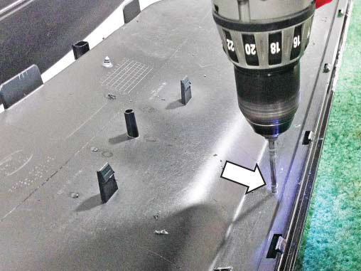
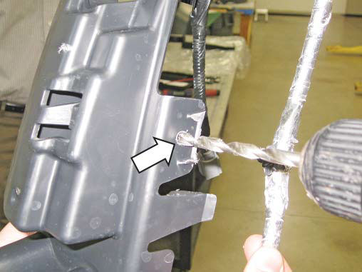
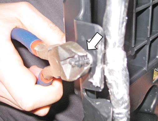
38. Drill a 1/4" hole as shown below, reinstall the push-in retainer and then trim the excess.
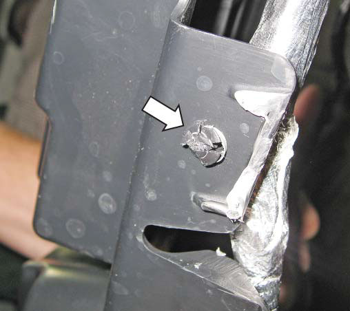
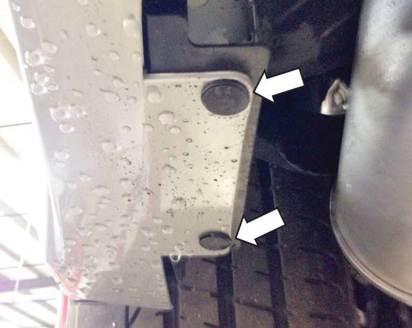
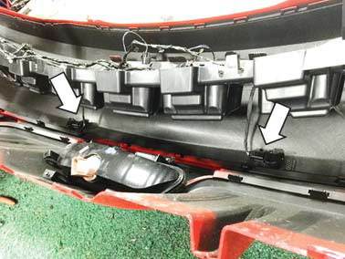
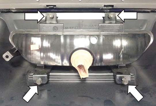
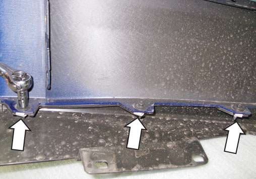
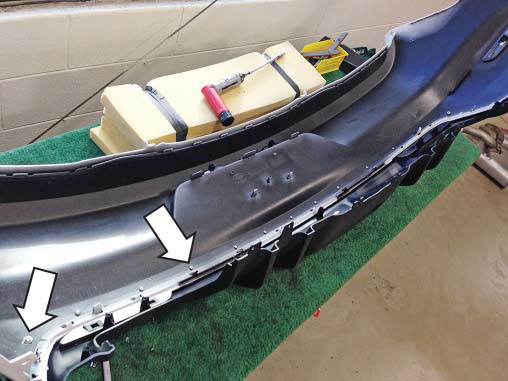
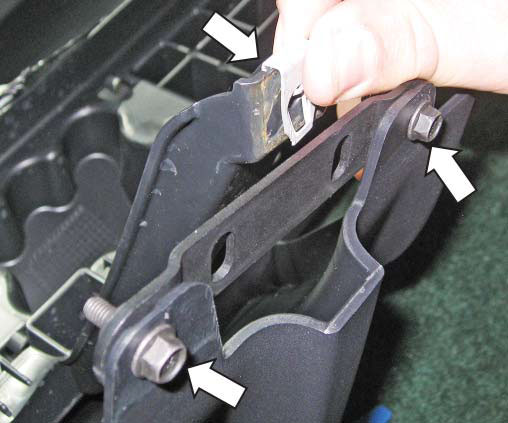
39. Install one (1) bracket (P/N: 1315-17F950), one (1) J-clip (P/N: N623332-S439), two (2) 7m screws (P/N: 98093A316) and one (1) 10mm screw (P/N: 98093A440) onto each side of the lower rear valance in order to secure it to the bumper cover reinforcement piece.
Section B- Installation
To install the bumper cover, reverse steps 1 through 10 with the exception of the two (2) push-in retainers that were removed in step 6. Congratulations!!! You have completed the installation of your new ROUSH Performance Products 2015 Mustang Rear Valance Kit.