 FREE 1 to 3-Day Delivery on Orders $149+ Details
How to Install SR Performance Front & Rear Sway Bars (94-04 All, Excluding 99-04 Cobra) on your Ford Mustang
Installation Time
6 hours
Tools Required
- Torque wrench with 10-60 ft/Lb torque range
- 9/16” Socket (Rear new sway bar bolts)
- 5/8” Socket (Front sway bar bracket bolts)
- 14mm Socket (Front new sway bar links)
- 15mm Socket (Front stock sway bar links)
- 13mm Socket (Stock rear sway bar bolts)
- 14mm Open ended wrench (Rear new sway bar nuts)
- Adjustable Wrench (End link bolt)
- Socket wrench ratchet (Various applications)
- Needle nose pliers (To remove flexible brake line and to hold and align rear sway bar bolts)
- Floor jack
- Jack stands
- Penetrating grease
- Breaker bar (If necessary)
- Ratchet extenders (Various applications)
SR Performance Front & Rear Sway Bars (94-04 All, Excluding 99-04 Cobra)
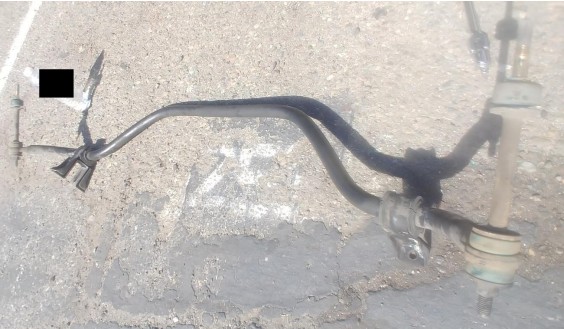
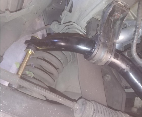
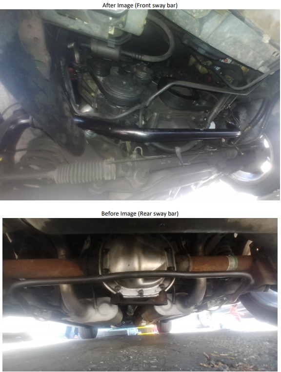
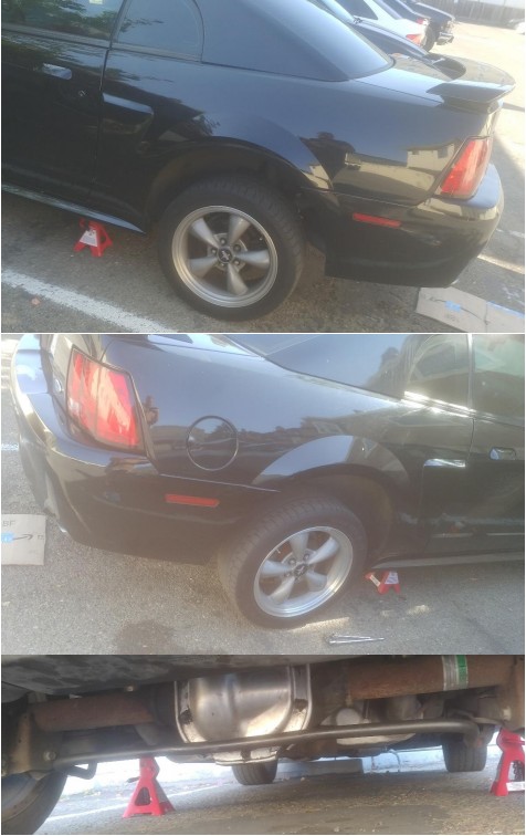
Before Image (Front sway bar)
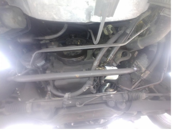
Installation Instructions (Front sway bar):
1. Instruction one: Jack up car and place jack stands on each side of vehicle for better access to bolts.
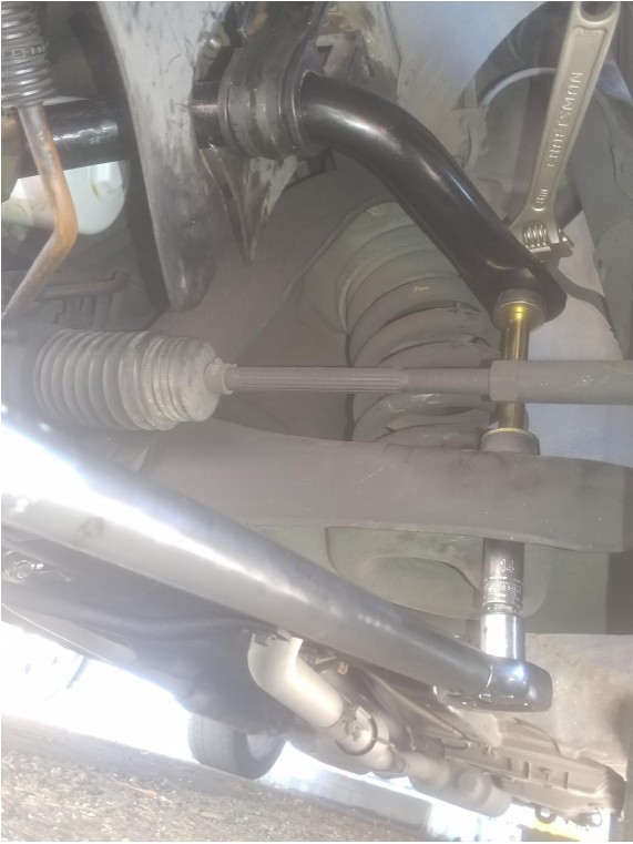
2. Instruction two: Use an adjustable wrench to hold the top bolt of the sway bar link and a 15mm socket connected to a ratchet on the lower end of the end link. Loosen the bolts to remove the end link from the lower control arm.
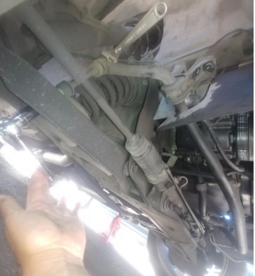
3. Instruction three: Use a 5/8” socket and ratchet to remove the sway bar brackets. Use penetrating oil and a breaker bar if needed.
4. Instruction four: remove stock sway bar and set aside.
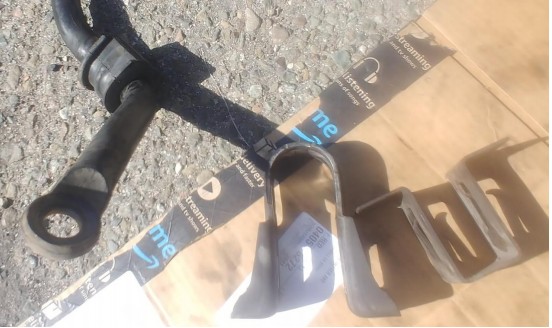
5. Instruction five: Remove stock sway bar brackets by removing the inner bracket and then pushing the outer bracket off the bushing. This is a good time to clean up the brackets with a rag.
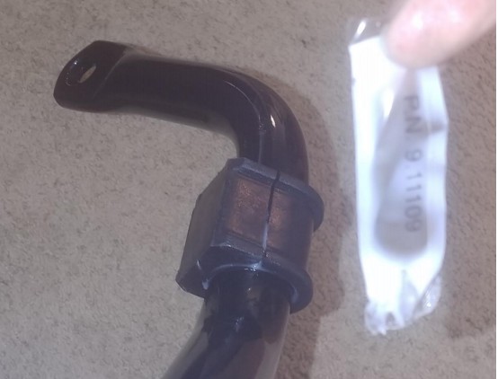
6. Instruction six: Apply the provided bushing lubricant (P.N. 9.11109) to the inside diameter of the new front sway bar bushings. Open the bushing and wrap it around the new front sway bar at the section just after where the bar connects to the end links.
7. Instruction seven: Place the outer bracket around the curved portion of the sway bar bushing.
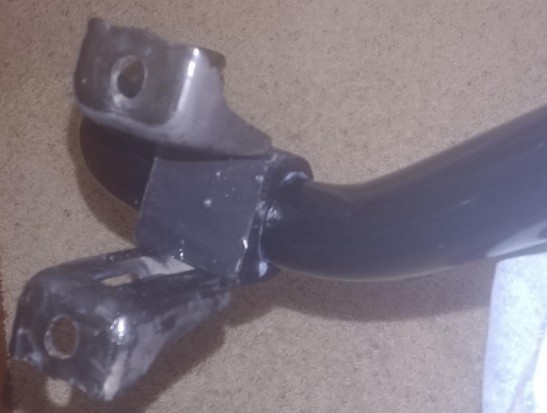
8. Instruction eight: place the inner bracket inside the outer bracket against the flat portion of the sway bar bushing.
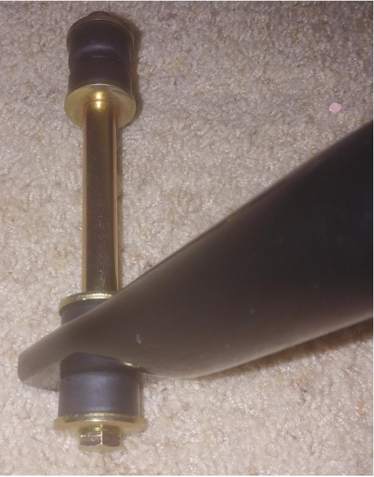
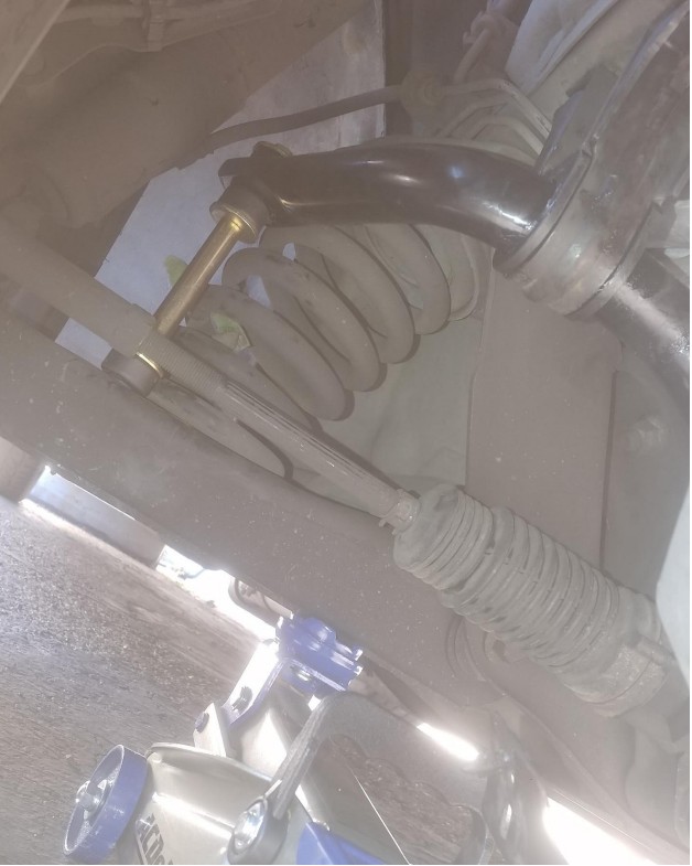
9. Instruction nine: Remove all end link components (Washers, bushings, nut and spacer) and then reassemble the components onto the end of the sway bar with the bolt closest to the bar and the nut farther away from the bar as show in the photo below.
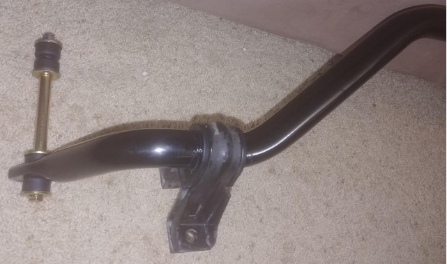
10. Instruction ten: The new sway bar is ready to install in your mustang.
11. Instruction eleven: Remove the end link nut, washer and bushing closest to the nut and insert the bolt through the lower control arm end link hole. At this time also align the bracket holes with the bolts and twist the bracket nuts onto the bracket bolts by hand to hold up the sway bar.
Note: This step is much easier with a buddy because the bar is heavy, and your buddy can do the other side simultaneously to get the bar into place and secured.
12. Instruction twelve: Push the end link bolt down through the control arm hole. If the bolt will not push through with enough slack to add the lower bushing, washer and nut use a jack to push up the lower control arm and push down on the end link to get enough slack through to secure the bushing, washer and nut.
13. Instruction thirteen: Make sure the sway bar is centered and then use a torque wrench with a 5/8” socket set to a torque between 44-59 ft/lbs (52 ft/lbs is the average and should be sufficient) and then torque down the sway bar bracket nuts on both sides.
14. Instruction fourteen: Use an adjustable wrench to hold the upper end link bolt and a torque wrench for the lower end link nut with a 14mm socket set to a torque between 11-16 ft/lbs (Using 11 ft/lbs is sufficient because the rubber bushings can sometimes absorb some of the pressure increasing the amount of torque required) and torque down the end link on both sides. At this time your front sway bar is installed and good to go!
Installation Instructions (Rear sway bar):
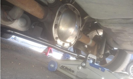
1. Instruction one: Use a jack to jack up both sides of the vehicle and use jack stands to hold up the rear of the car for better access to the rear sway bar bolts at the lower control arm.
2. Instruction two: Use penetrating grease if the two bolts are too difficult to remove with a breaker bar.
3. Instruction three: Use a ratchet and a 13mm socket to remove the stock sway bar bolts.
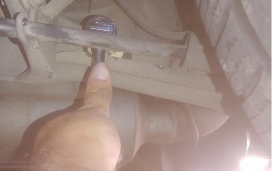
4. Instruction four: Remove stock sway bar.
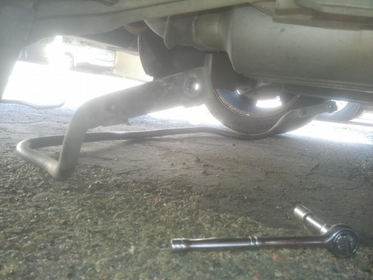
5. Instruction five: Place both ends of the new sway bar in lower control arm slots and put the two bolts closer to the front of the vehicle through the control arm holes and sway bar holes just to secure the bar for now. Use a floor jack to hold up the bar for stability and to align the holes closest to the rear of the vehicle.
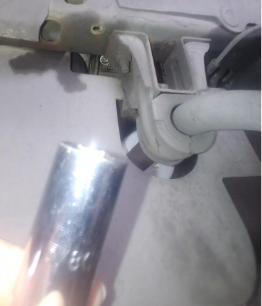
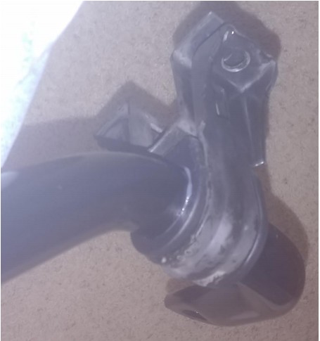
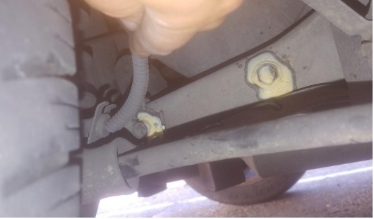
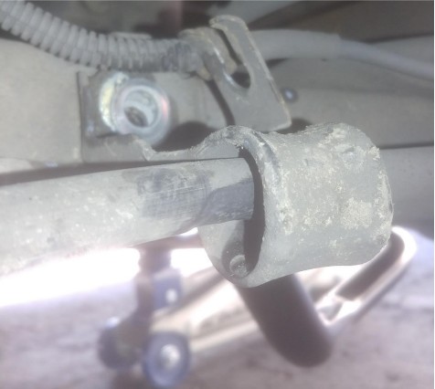
6. Instruction six: Remove the rubber brake line holder from the forked bracket to free up space for your torque wrench.
7. Instruction seven: Put the remaining two bolts through the sway bar holes closest to the rear of the vehicle (use a floor jack to get the holes aligned) and align all four of the bolts and nuts between the inside of the lower control arm and the sway bar with a set of needle nose pliers and twist to secure.
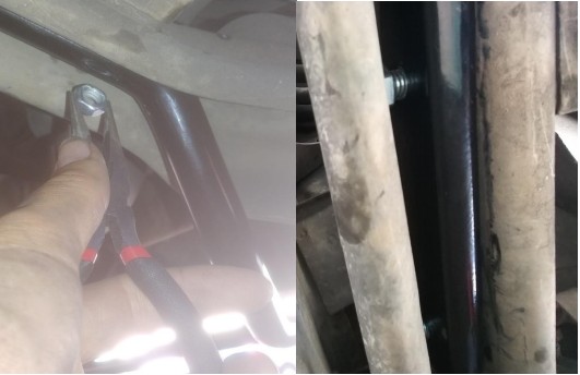
8. Instruction eight: Use a 14mm open end wrench and a 9/16” socket and ratchet to secure the four sway bar bolts and nuts.
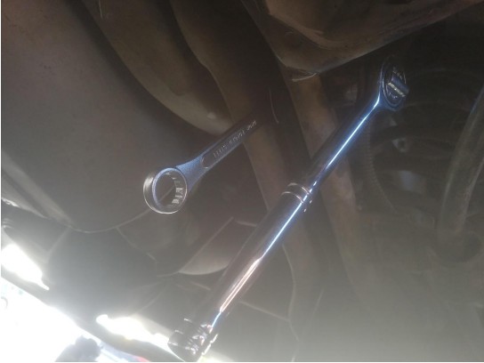
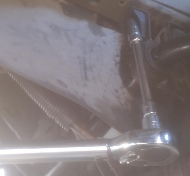
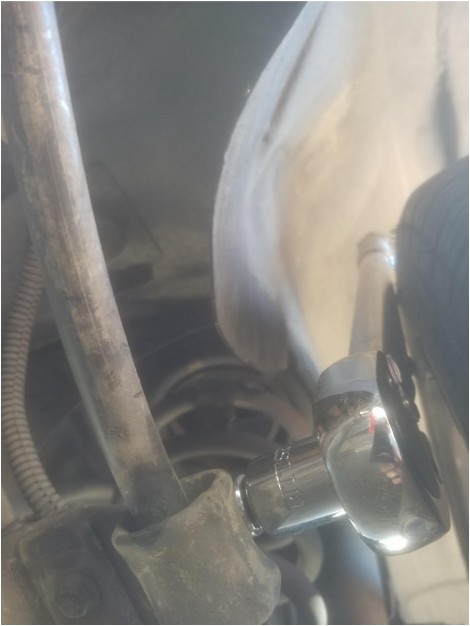
9. Instruction nine: Use a 14mm open end wrench and a torque wrench with a 9/16” socket to torque the bolts within a range of 29-37 ft/lbs (33 ft/lbs is the average and should be sufficient). For the bolts nearest the front of the car extenders can be used to get the torque wrench outside the body of the car to torque the bolts and nuts.
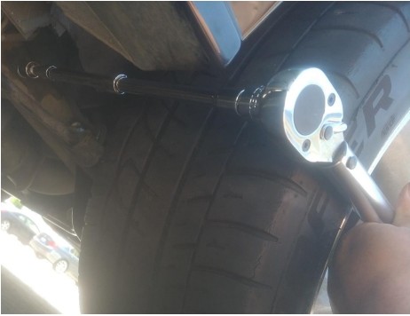
10. Instruction ten: For the bolts near the rear of the vehicle the torque wrench can be placed behind the tire in the wheel well. Secure these bolts using the same torque described in the previous step (Instruction nine), and the same 14mm open ended wrench and torque wrench with 9/16” socket.
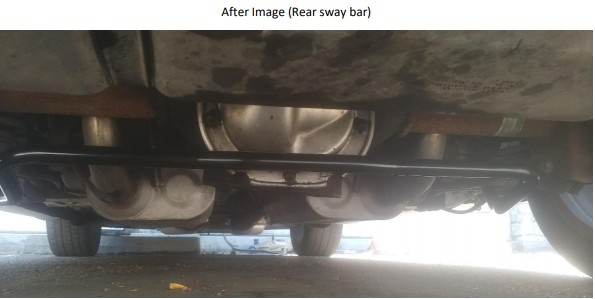
11. Instruction eleven: Reinsert the rubber brake line holder into the forked bracket (removed from instruction six). At this point your installation is completed!
Installation Instructions Written by AmericanMuscle Customer Micah Baca 07/04/2019
