 FREE 1 to 3-Day Delivery on Orders $149+ Details
How to Install AFE Momentum GT Pro 5R Cold Air Intake (15-17 EcoBoost) on your Ford Mustang
Tools Required
- 8mm nut driver
- 7mm nut driver
- 10mm deep socket & driver
- 11mm deep socket
- 20mm socket & wrench
- adjustable wrench
- flat head screwdriver
- pliers or spring clamp tool
- anaerobic liquid pipe sealant or teflon tape

Shop Parts in this Guide
• Please read the entire instruction manual before proceeding.
• Ensure all components listed are present.
• If you are missing any of the components, call customer support at 951-493-7100.
• Ensure you have all necessary tools before proceeding.
• Do not attempt to work on your vehicle when the engine is hot.

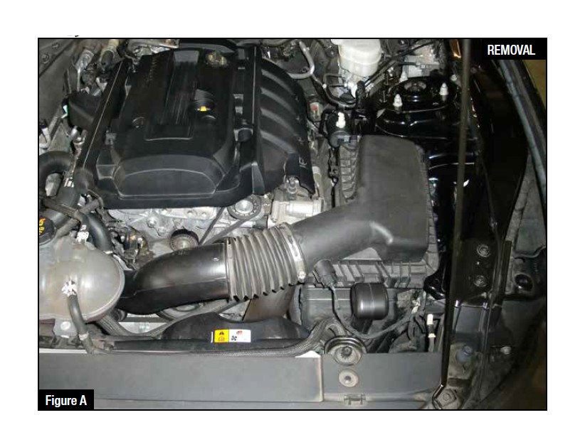
Refer to Figure A for Step 1
Step 1: Loosen the two clamps on the intake tube. One at the turbo and one at the air box.
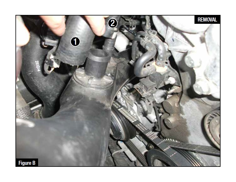
Refer to Figure B for Steps 2-3
Step 2: Using pliers (or a spring clamp tool) remove the spring clamp from the large 1" rubber hose. Keep the spring clamp on the rubber hose because it will be reused in a later step. 1
Step 3: Push the release button on the Crank Case Vent connector and pull up on the tube, to remove the connecter from the SAE fitting on the stock intake tube. 2
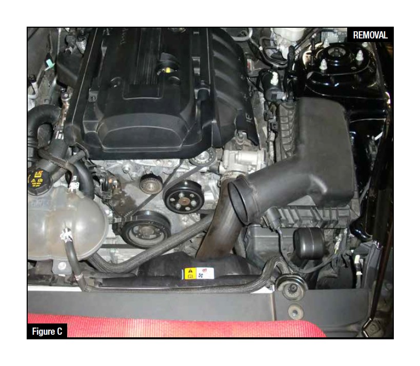
Refer to Figure C for Step 4
Step 4: Remove the stock intake tube from the vehicle
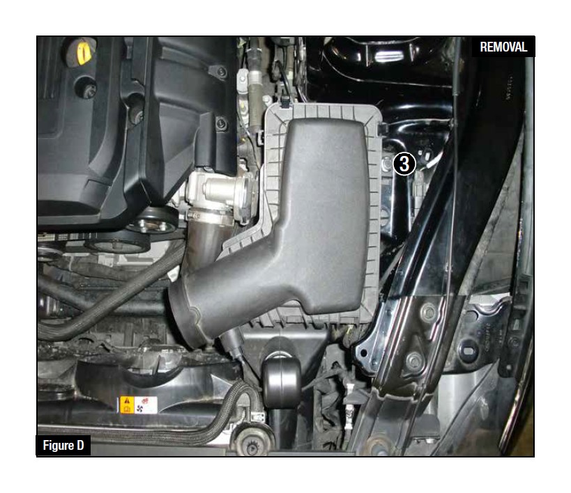
Refer to Figure D for Steps 5-7
Step 5: Remove the 10mm bolt on the side of the air box. 3
Step 6: Disconnect stock temp sensor harness from the sensor and the air box.
Step 7: Pull the air box out of the vehicle by lifting straight up on the air box
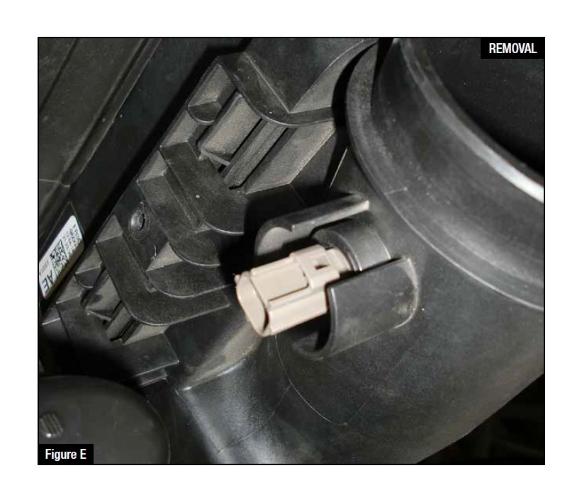
Refer to Figure E for Step 8
Step 8: Remove the temp sensor from the air box by twisting it a 1/4 turn counterclockwise and pulling straight out. Store the temp sensor in a safe place so that it can be reused with your new aFe intake system.
CAUTION: Do NOT break the small plastic tab on the sensor.
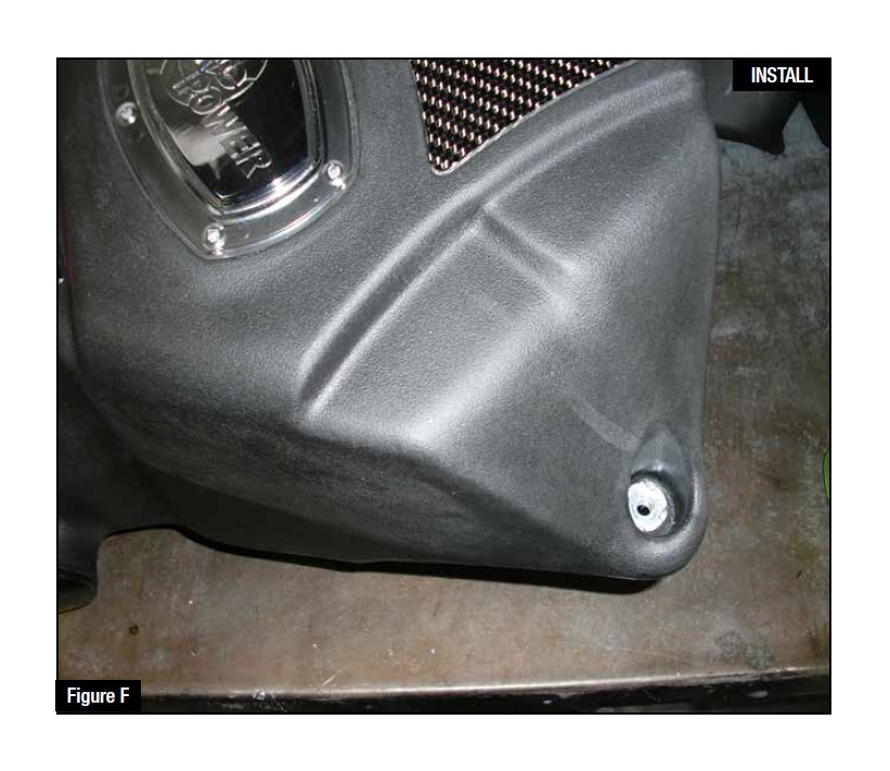
Refer to Figure F for Steps 9-10
Step 9: Remove the stock rubber grommet and metal sleeve from the factory air box and install them in the same orientation into the new aFe air box.
Step 10: Remove the rubber guide bushing from the post on the bottom of the factory air box.
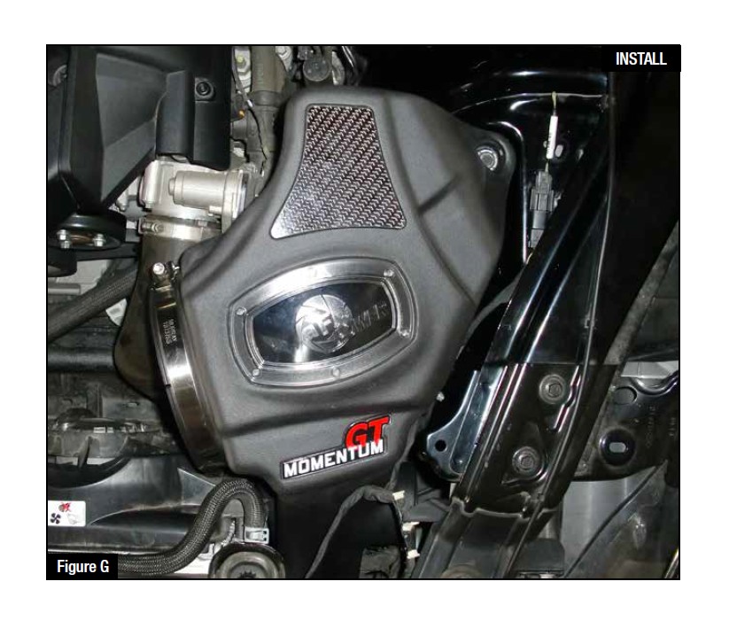
Refer to Figure G for Steps 11-13
Step 11: Install the rubber guide bushing into the large hole on the inner fender well.
Step 12: Install the new aFe air box. Make sure to line up the front snorkel to the factory air-inlet that is underneath the front core support.
Step 13: Secure the housing with the stock 10mm screw that was removed in a previous step.
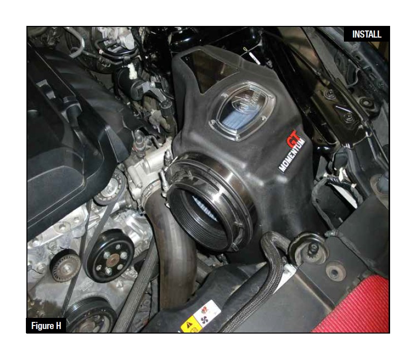
Refer to Figure H for Steps 14-15
Step 14: Slide the new aFe air filter into the air box.
Step 15: Do not tighten clamps at this time, but make sure both clamps are oriented the same direction and that they are easily accessible for tightening later.
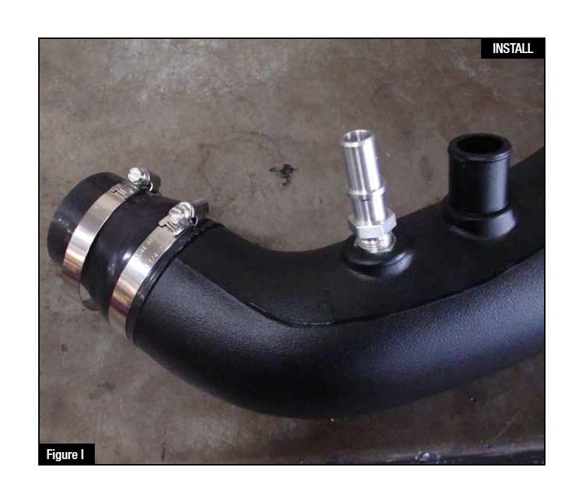
Refer to Figure I for Steps 16-18
Step 16: Prepare the intake tube by installing the new billet aluminum SAE fitting into the threaded insert on the aFe intake tube (see not below). Do not overtighten the SAE fitting.
Step 17: Place the new silicone coupling onto the small end of the new aFe intake tube.
Step 18: Put both clamps in place as shown but do not tighten the clamps at this time. Make sure both clamps are oriented so that they will be accessible after the tube is installed.
NOTE: Apply a stripe of an anaerobic liquid pipe sealant around the male threads leaving the last two threads uncovered. If no liquid sealant is available, wrap Teflon tape 1-1/2 turns in a clockwise direction, viewed from the pipe end, leaving the last two threads uncovered.
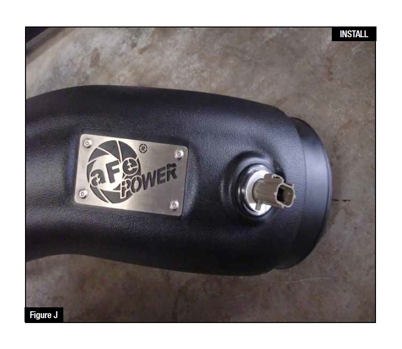
Refer to Figure J for Steps 19-21
Step 19: Install the provided rubber grommet into the large hole on the front of the new aFe intake tube.
Step 20: Install the provided billet adaptor for the temperature sensor (not orientation dependent)
Step 21: Install your factory temperature sensor into the billet adaptor and turn the sensor 1/4 turn clockwise to lock it into place. The small plastic tab on the temp sensor will lock over the small hump on the adaptor when installed correctly.
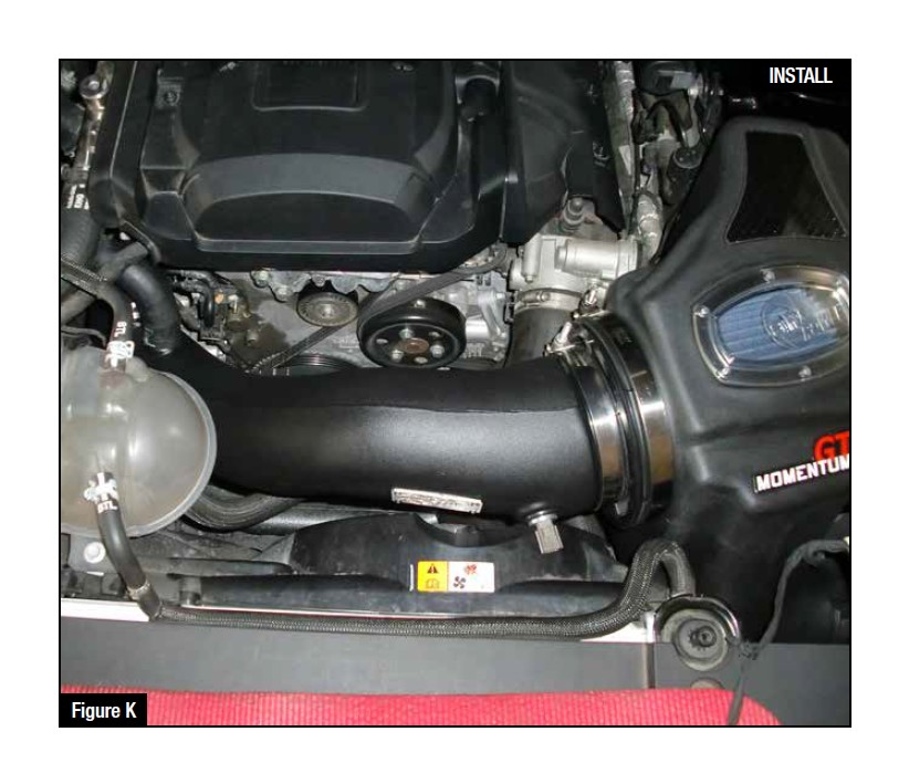
Refer to Figure K for Step 22
Step 22: Install the intake tube into the vehicle. It is best to install the filter end of the intake tube first, and then install the turbo end of the intake tube. Make sure that all clamps are loose during this step to insure ease of install.
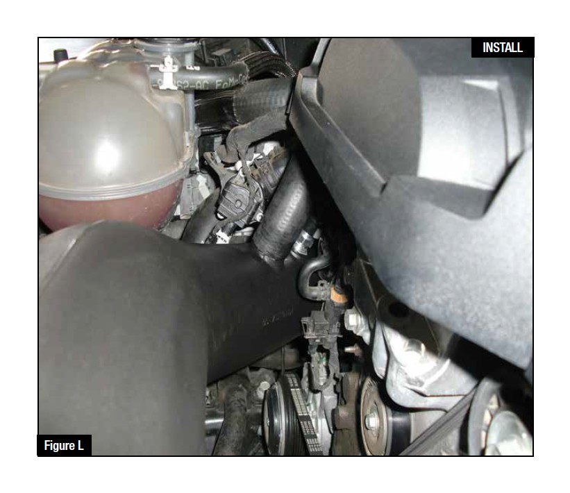
Refer to Figure L for Steps 23-24
Step 23: Plug in the CCV into the new billet aluminum SAE fitting. It will make a clicking sound when it is locked on. You may use silicone spray or WD-40 on the O-Ring and/or the fitting to allow this connection to lock on easier.
Step 24: Reconnect the large rubber bypass hose to the new aFe intake tube and secure it with the stock spring clamp that was removed in a previous step.
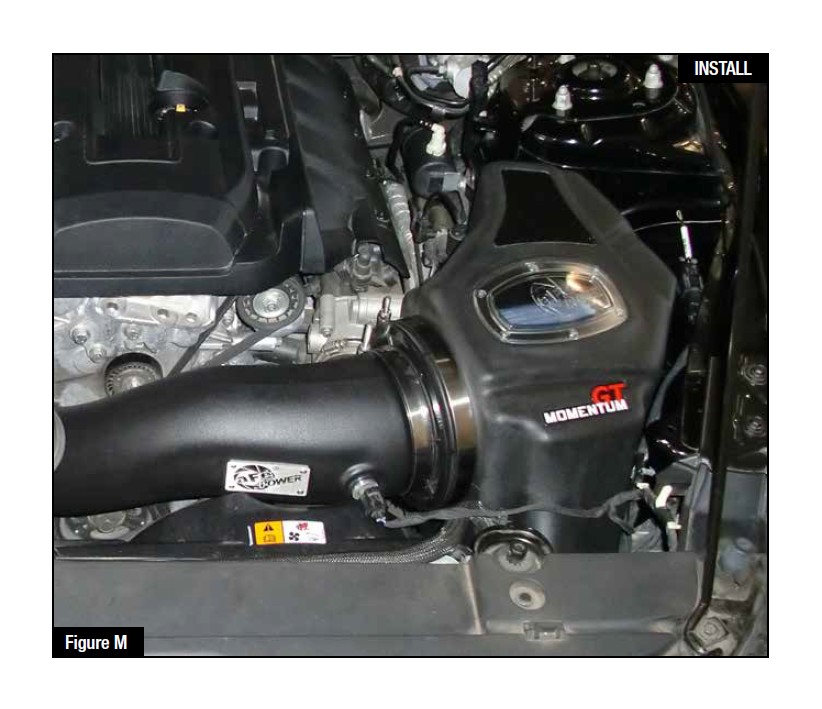
Refer to Figure M for Steps 25-27
Step 25: Tighten all clamps at this time.
Step 26: Plug in temperature sensor. Check that all of the components are tight and secure. Your installation is now complete. Thank you for choosing aFe Power!
Step 27: (Optional) Install the plug into the side of the air box to get the coldest air possible.
NOTE: Check all bolts, clamps and connectors after 200 miles.
