 FREE 1 to 3-Day Delivery on Orders $149+ Details
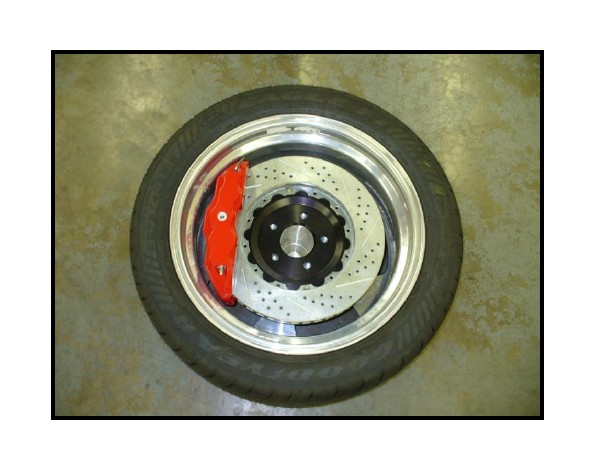
How to Install Baer Extreme Plus Front Brake Kit - Silver (05-14 All) on your Ford Mustang

Shop Parts in this Guide
ATTENTION: Read this before going any farther! Returns will not be accepted for ANY installed PART or ASSEMBLY. Use great care to prevent cosmetic damage when performing wheel fit check. In the event that a product must be returned, please contact Baer Customer Service for a RMA Number.
Notices – Read and Follow BEFORE ATTEMPTING INSTALLATION
All installations require proper safety procedures and protective eyewear.
All installations assume basic mechanical skill and a factory service manual for the vehicle on which the installation is to be performed.
All references to the “left” side of the vehicle correlate to the driver’s side of the vehicle.
Any installation requiring you to remove a wheel or gain access under the vehicle requires use of jack stands appropriate to the weight of the vehicle. In all cases, jack stands rated for a minimum of 2-tons is recommended.
A selection of hand tools sufficient to engage in the installation of these products is assumed, and is the responsibility of the installer to have in his/her possession prior to beginning this installation. All installations, which require removal of hydraulic hoses and/or bleeding of the brakes, require appropriate fitting/line wrenches, safety catch can, and protective eyewear. Other than these items, if unique or special tools are required they will be stated appropriately in the installation step.
ALWAYS CONFIRM WHEEL FIT PRIOR TO BEGINNING INSTALLATION OF ANY BRAKE SYSTEM OR “UPSIZED” ROTOR UPGRADE! In addition to checking wheel fitment (available online at www.baer.com), always place the actual corner assembly or a combination of the caliper assembly onto the rotor, and into the actual wheel. This procedure will reconfirm proper clearance between the caliper and the wheel before proceeding with the actual installation.
Returns will not be accepted for systems that have been partially or completely installed. Use extreme care when checking wheel fitment to prevent any cosmetic damage.
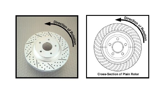
When installing rotors on any Baer Products be sure to follow the direction of rotation indicated on the rotor hat area with either an arrow, or an “L” for left, or an “R” for right, or both. “L” or left always indicates the driver’s side of US spec vehicles. Images shown are “L” left rotors:
A proper professional wheel alignment is required for any system requiring replacement of the front spindles, or tie rod ends. Follow factory prescribed procedures and specifications unless otherwise indicated.
At all times stop the installation if anything is unclear, or the parts require force to install. Consult directly with Baer Technical Staff in such instances to confirm details. Please have these instructions, as well as the part number machined on the component that is proving difficult to install, as well as the make, model, and year (date of vehicle production is preferred) of your vehicle available when you call. Baer’s Tech Staff is available from 8:30-am to 5-pm Mountain Standard Time (Arizona does not observe Daylight Savings Time) at 602 233-1411 Monday through Friday.
INSTALLATION:
1. Disconnect the brake hose from the hardline at the frame and cap with the supplied vinyl cap. Use a line wrench to avoid rounding the tube nut.
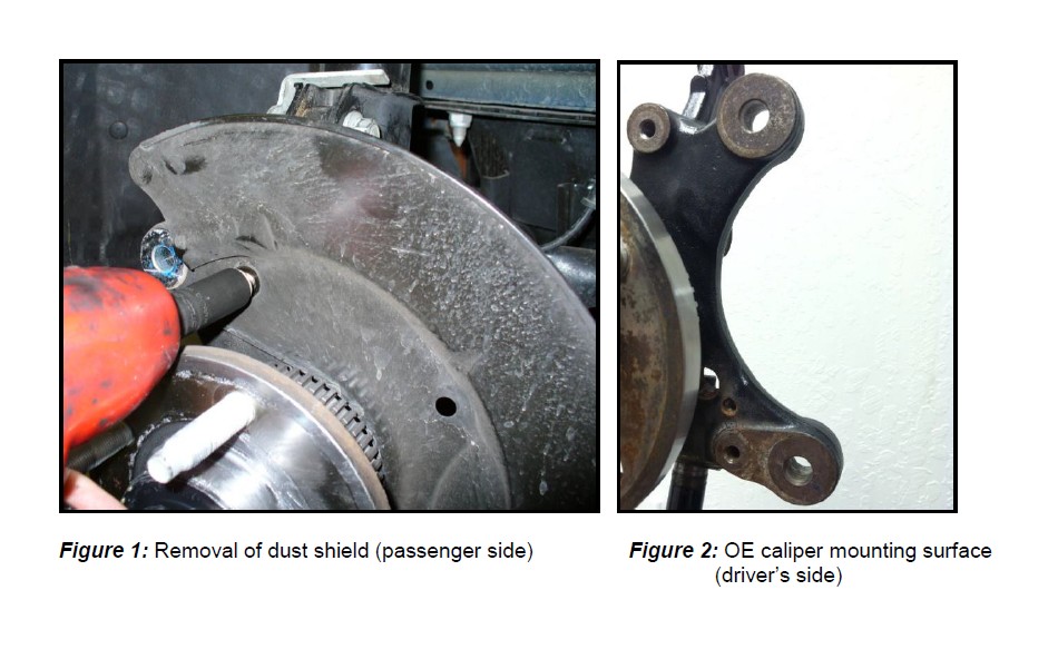
2. Remove the caliper and anchor assembly from the spindle. Next, remove both the OE rotor and dust shield (see Figure 1 for reference).
3. Next, thoroughly clean the hub surface and OE caliper mounting surface. This will allow the new components to seat properly. See Figure 2 for reference.
4. Remove the radial mount bracket from the new caliper (this was installed onto the caliper for ease of shipment).
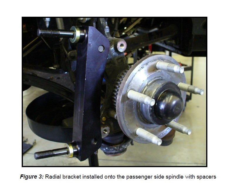
5. Install the radial mount bracket to the outboard side of the spindle using the original anchor bolts and the supplied 7/16” washers. This will prevent bolt contact with the rotor. Torque each bolt to 85 ft∙lbs. See Figure 3 for installation reference.
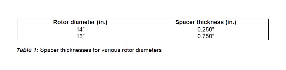
6. Install the spacers onto the radial mount studs that correspond to your new brake system. See Table 1 below, for reference:
7. Install the correct side rotor onto the hub. Secure with three lug nuts and washers to avoid scratching the rotor hat.
8. With pads installed, slide the caliper side caliper over the radial mount studs and onto the bracket. Secure with the supplied washers and 12-point nuts. Torque each nut to 75 ft∙lbs.
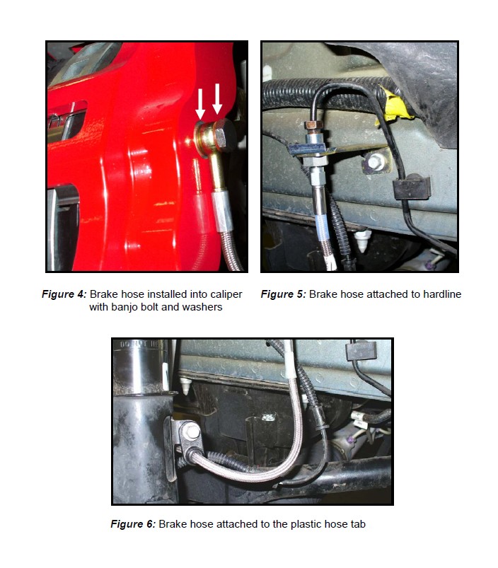
9. Finger tighten the steel braid banjo hose end with one copper washer on each side of the banjo fitting into the rear of the caliper. Connect the hose to the hardline at the frame and install the hose lock. Attach the plastic hose tab to the strut with the factory bolt. **IMPORTANT: Position the hose to avoid interference with the wheel and suspension components through the entire range of motion. Tighten fitting and banjo bolt to 15-20 ft∙lbs. See Figures 4-6 for reference, on continued page.
Refer to Bleeding, and Pad Bedding & Rotor Seasoning Procedures contained on a separate sheet, or on www.baer.com
