 FREE 1 to 3-Day Delivery on Orders $149+ Details
Competition Engineering Mustang Subframe Connectors ('05-'11) - Installation Instructions
Installation Time
3 hours
Tools Required
- (1) Frame Connector, Left
- (1) Frame Connector, Right
- (4) 3/8IN.X 4-1/2IN. Bolts
- (4) 3/8IN. Nyloc Nuts
- (8) 3/8IN. Washers Flat
- (2) Rocker Panel Nut Plates
- (8) 3/8IN. Washers Split
- (4) 3/8IN. X 1IN. Bolt
- (2) 14MM X 90MM Bolts
- (2) Aluminum Pocket Spacers
- (2) Shim Plate .059 thick
- (2) Shim Plate .032 thick
- (2) Stop Plate
- (4) 10MM Bolts
- (2) Frame Brace Plate
- (2) M6 X 12 Self Tapping Screws
- (2) M8 X 20 Self Tapping Screws
Installation
Installation Instructions - WELD-IN:
1. Place the transmission in neutral and hoist the vehicle into position utilizing the auto manufacturer’s recommended lift points and the lift manufacturer’s safety instructions.
2. Remove the brake cable brackets by first removing the cable bracket retaining bolts and secure the brake cables out of the way.
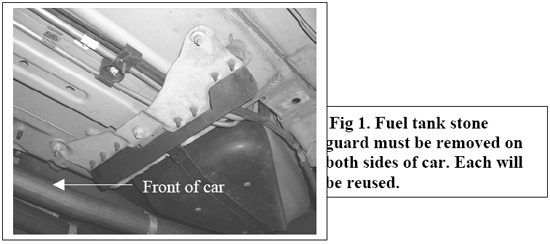
3. Remove the left and right, fuel tank stone guards. Safeguard the hardware. See Fig. 1
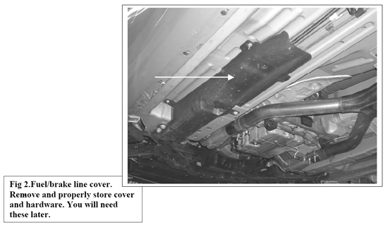
4. Remove the fuel/brake line cover (on driver’s side). See Fig. 2
Note:You will need to carefully move this out of position. Some prying may be necessary. Be patient it does come out.
5. Cut outer rear stone shield mounting stud from floor of car. Repeat on other side of car.
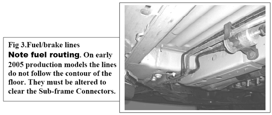
Note:Depending on the production date of your car, your fuel lines may or may not be bent to follow the contour of the floorboard. Early production models of 2005 have straight fuel lines that will have to be altered to clear the frame connectors. See Fig. 3
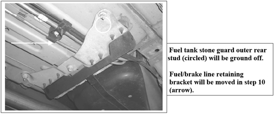
6. Cut off outer fuel tank stone guard, mounting stud on both sides of car. See Fig. 4
7. Remove rear control arm retaining nut (located on front of rear control arm).
Note:Removing the control arm bolt can be achieved more easily with the use of a tie down strap.
8. Hook one end to the transmission crossmember and secure the other end around the rear end housing. Tightening the tie-down strap will relieve some of the pressure on the bolt. See Fig. 5

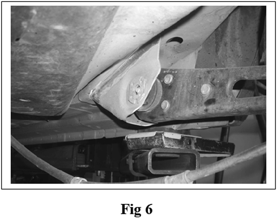
8. Trim the ears off the nut retainer with a grinder. Fig. 6 shows control arm pocket with nut retainer removed.
Note:Only remove (1) control arm retaining bolt at a time.
10. Unbolt the fuel line retaining bracket, See Arrow Fig 4
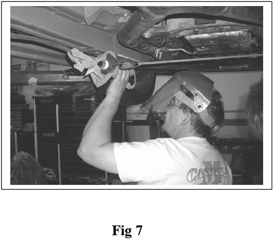
11. Move the fuel and brake lines out of the way and protect them from welding heat and sparks, cover with a heat resistant material. See Fig 7
12. Trial fit the Sub-frame Connectors in place.
13. There are several holes that have to line up. The Sub-frame Connector will have to be lined up from left to right and front to back.
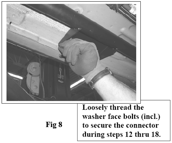
14. Use the enclosed Washer Faced Metric Bolts to temporarily hold the connector in place while marking the outline of the connector pockets and front rocker/frame bracket on the car.
Note:There are (2) threaded holes in the rocker panel that the Washer Face Bolts thread into. They will be used in the final installation also. See Fig 8
15. Temporarily install the forward most rear control arm bolt.
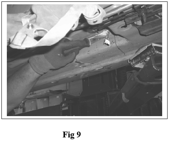
16. Use a marker and draw around the frame connector pockets and mounting brackets to show all areas that must be cleaned to bare metal before welding can begin. Do this same step on the other side of the vehicle also.
17. Check fit of the Sub-frame Connector against the rockers, floor panel, and over the frame pocket on rear frame. Now remove Sub-frame Connector from this side of the car. Replace control arm retaining bolt and loosely reinstall the control arm retaining nut.
Note:It may be necessary to shim the rocker panel brackets on some vehicles, due to production variances from vehicle to vehicle. Use shims included in this kit. Use enough shims to ensure a flat surface to bolt the Sub-frame Connector to during installation.
18. Clean all areas to be welded. Remove seam seal with putty knife.
19. Ensure all undercoat, grease, oil, and grinding dust have been removed.
20. Repeat steps 12 thru 19 on the other side of the car. Remember: Do not remove both control arm mounting bolts at the same time.
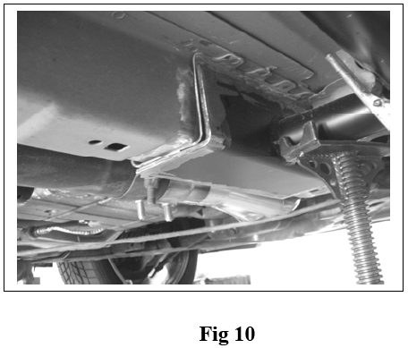
Note:Tall screw type jack stands will prove their value in holding power and convenience as they are used to keep the Sub-frame Connectors in position during fit up and welding. Fig 10
21. Remove the carpet and underlayment before beginning any welding (this is where a helper comes in handy). Have the helper stay along side the car to watch that there is no problems inside the car from welding hot spots.
Note:Both Battery cables should be disconnected at this time. Do not proceed without disconnecting both battery cables.
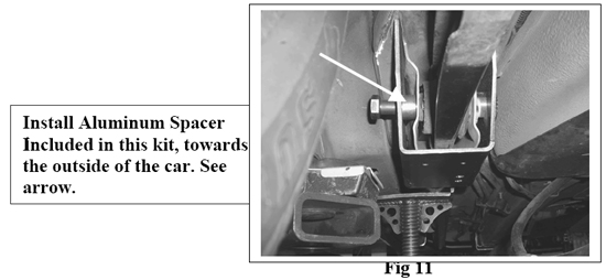
22. Re-install the Sub-frame Connectors to include the rear control arms and the Aluminum pocket spacers included in this kit. Spacer goes toward outside of car between the Subframe Connector Pocket and the frame pocket.(See Arrow in photo) See Fig 11
Note:Before welding in the Rear Bracket Pocket, protect the fuel tank from the welding heat and sparks by using a heat barrier. We used a formed sheet of steel and placed it between the tank and the frame. Tack-weld the Sub-frame Connectors in the car one side at a time, being mindful of interference with other parts. Tack in both sides and step back taking one final look at how everything fits.
23. With both Sub-frame Connectors tacked in place and rear control arms loosely installed. check the installation a final time. If you are confident that the installation is correct. Begin finish welding the connectors.
24. Give the Sub-frame Connectors a chance to cool down before continuing.
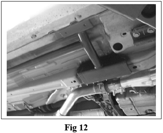
25. It is a good idea to prime and paint the Sub-frame Connector in the areas that were welded as we did. See Fig 12
26. All bolts should be installed at least finger tight, at this point. Tighten and or Torque all bolts.
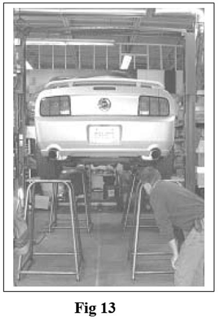
Note:The weight of the car should be on the suspension with vehicle at ride height, while torquing the bolts. We placed our car on scale tables to torque the bolts. See Fig 13. The control arm bolt torque is 129 lb.ft.
27. After torquing the rear control arm bolts, install the stop plates included in this kit. The hex shape hole in the center of the plate is placed over the hex head of the control arm bolt. Rotate the Stop Plate until one of the smaller outer holes line up with the hole in the Frame Connector. See Fig 14
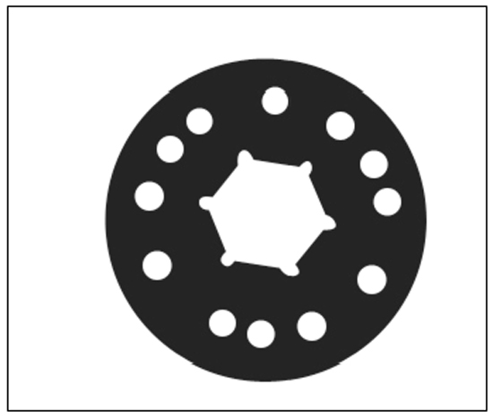
28. Secure with 6MM Self Tapping Screws included in kit. Repeat step on other side.
29. Bolt the emergency brake bracket to the bottom of the Sub-frame Connector Pocket using the 8MM Self Tapping Screw. Repeat step on opposite side.
30. Replace the fuel line/brake line bracket.
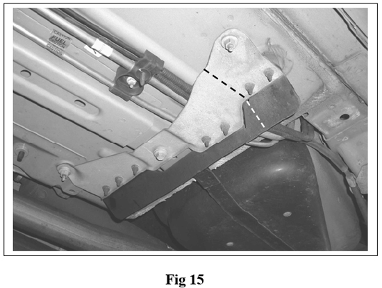
31. The fuel tank stone guards must be altered in order to clear the Sub-frame Connector. Fig 15 shows where the stone guard must be cut. This step may take a couple of attempts but test fit each piece until you are happy with the fit and bolt them back into the car. Repeat procedure on other side. See Fig 15
32. Replace fuel/brake line cover on driver’s side.
Note:This cover will also need to be trimmed to clear the cross-over tube located at the front of the Sub-frame Connector. Use a good pair of tin snips.
33. Lower car and replace the parts of the interior that were removed.
34. Reconnect battery terminals.
35. Test drive car.
Installation Instructions: BOLT-IN
Follow steps 1 thru 9, then these instructions.
1. Trial fit the Sub-frame Connectors in place.
2. There are several holes that have to line up. The Sub-frame Connector will have to be lined up from left to right and front to back.
3. To help keep the Sub-frame Connector in place, loosely install the 8MM bolts through the rocker panel mounting bracket and into the threaded, rocker panel factory holes.
4. Position the Sub-frame Connector rear pocket over the factory frame pocket and insert the aluminum spacer. Install spacer towards the outside of the car.
5. Install front control arm bolt through the Frame Connector, Spacer and factory control arm and secure with nut.
6. Support the front portion of the frame connector with a tall set of jack stands.
Note:It may be necessary to shim the rocker panel brackets on some vehicles, due to production variances from vehicle to vehicle. Use shims included in this kit. Use enough shims to ensure a flat surface to bolt the Sub-frame Connector to during installation.
7. Drill (2) holes in the rocker panel using the Frame connector pocket as a guide.
8. Drill a 7/8” access hole in the rocker 1-5/8” behind the rear most hole that you just drilled.
9. Drill (2) holes through the frame rail. Use inner bracket of Sub-frame Connector as a template.
10. Bolt Inner Bracket to frame rail using supplied hardware.
11. Install frame brace plate to the inside of the frame rails. Insert 4-1/2” bolts through the frame connector, frame rail, brace plate and secure with supplied nuts.
12. Slide Rocker Panel Nut Plate through the access hole that was drilled earlier. Hold in place with your finger while installing the supplied 3/8” X 1” Bolts.
13. Repeat on opposite side of car.
14. Tighten all bolts. The control arm bolt torque is 129 lb.ft.
Note:The weight of the car should be on the suspension with vehicle at ride height while torquing the bolts. We placed our car on scale tables to torque the bolts. See Fig 13
15. Perform steps 27 thru 37 in the welding portion of these instructions.
Installation instructions provided by Competition Engineering
