FREE 1 to 3-Day Delivery on Orders $149+ Details
How to Install Flowmaster Delta Force Cold Air Intake (15-17 GT) on your Ford Mustang

Shop Parts in this Guide
REVIEW THE INSTRUCTIONS AND VERIFY THE KIT CONTENTS:
1. Please take a moment to read and understand these instructions before installing your Flowmaster cold air intake kit.
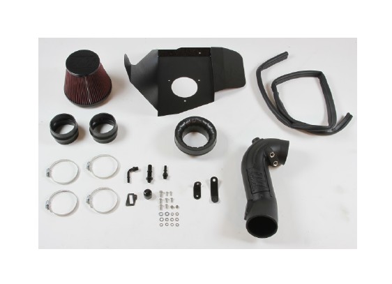
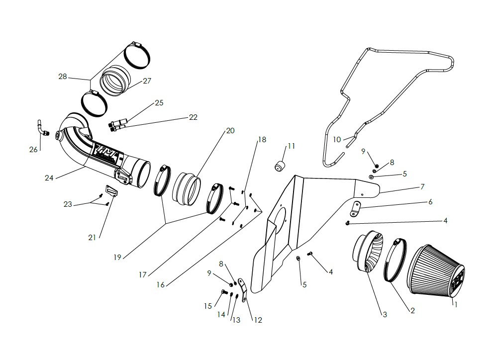
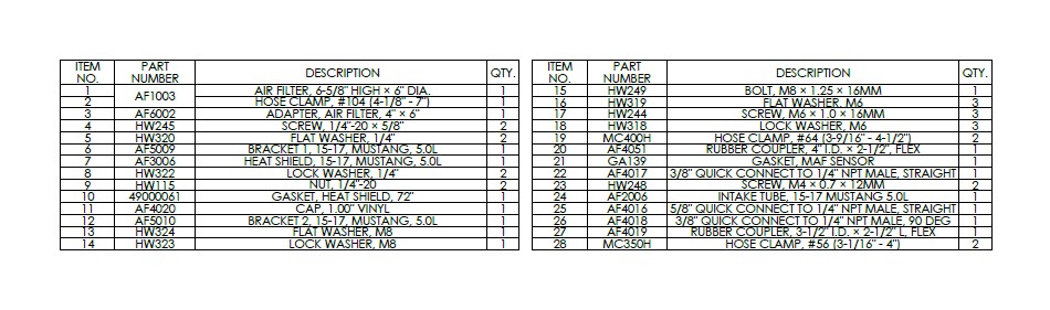
2. Use the parts drawing and list (front page) to verify your kit’s contents.
In the unlikely event that any parts are missing, please contact FLOWMASTER Technical Support for replacements.
To simplify assembly and avoid cross‐threading fasteners , identify and separate the ¼‐20 screws (item 4) (used with nuts (9)), and the M6 screws (17) (used with filter adapter (3)).
REMOVE THE FACTORY AIR INTAKE SYSTEM:
NOTES
• We highly recommend that you retain all factory air intake system parts.
• Please refer to vehicle manufacturer’s recommendations regarding removal of factory components.
• Disconnecting the negative battery cable erases pre‐programmed electronic memories. Write down all memory settings before disconnecting the negative battery cable. Some radios will require an anti‐theft code to be entered after the battery is reconnected. The anti‐theft code is typically supplied with your owner’s manual. In the event your vehicle’s anti‐theft code cannot be recovered, contact an authorized dealership to obtain your vehicle’s anti‐theft code.
3. Turn off the vehicle’s ignition and disconnect the negative battery cable.
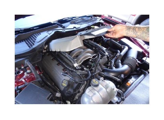
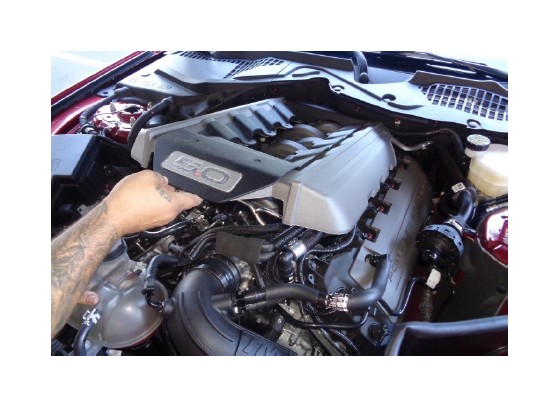
4. Remove the engine cover.
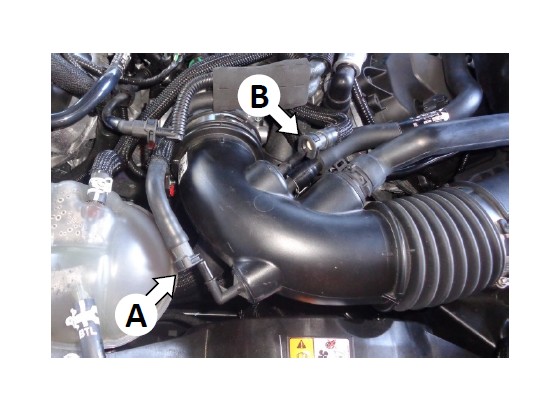
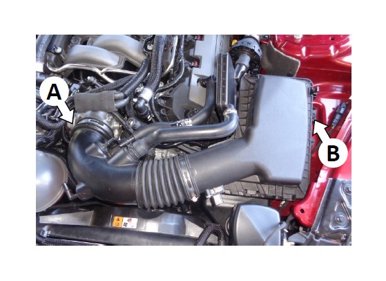
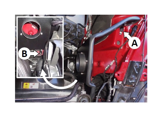
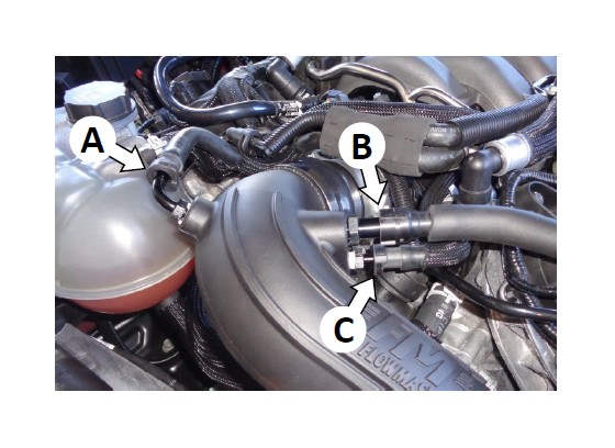
5. Disconnect the brake aspirator line (A) and EVAP line (B) from the air intake duct.
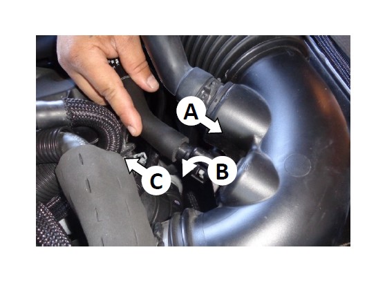
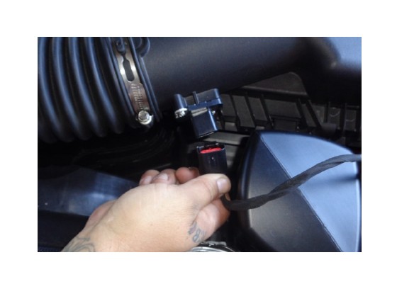
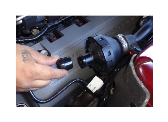
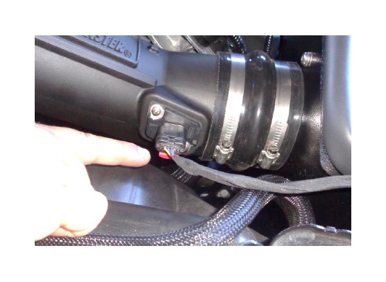
6. Disconnect the PCV line from the air intake duct by (A) pushing the fitting toward the duct, (B) releasing the latch, and (C) pulling line off the duct.
7. Remove and discard the metal clamp from the front resonator hose, then disconnect the hose.
8. Disconnect the mass airflow (MAF) sensor plug.
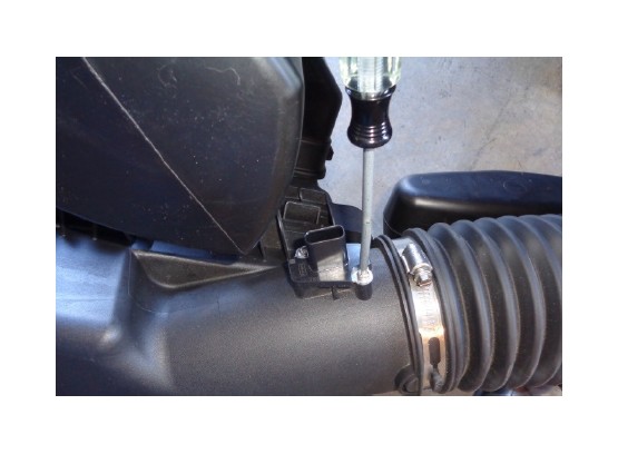
9. Loosen the hose clamp securing the air intake duct to the throttle body (A), then remove the bolt securing the airbox to the vehicle frame (B). Retain the bolt for later use.
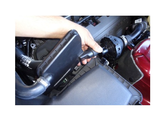
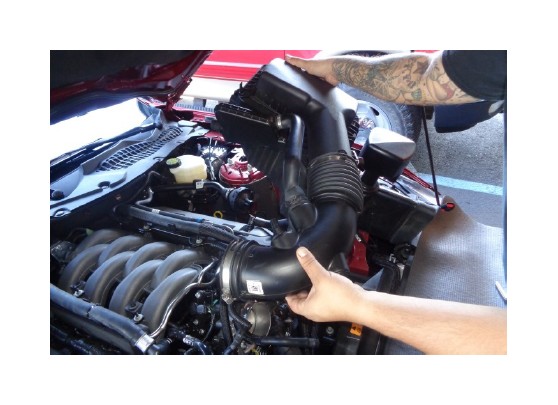
10.Disconnect the intake duct from the throttle body and remove the airbox and duct from the vehicle.
11.Remove the MAF sensor from the airbox, then remove the stock gasket from the sensor. CAUTION: The sensor is delicate! Handle it with care, and store it in a safe location until reinstallation.
ASSEMBLE AND INSTALL YOUR FLOWMASTER COLD AIR INTAKE SYSTEM:
12.Assemble air filter adapter (3) to heat shield (7) using M6 screws (17), lock washers (18) and flat washers (16).
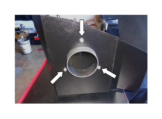
13. Attach bracket (6) to the heat shield using ¼‐20 screw (4) (on the bracket side), and flat washer (5), lock washer (8) and nut (9) (on the heat shield side). Do not tighten the fasteners at this time.
14. Attach bracket (12) to the heat shield using ¼‐20 screw (4) and flat washer (5) (on the heat shield side), and lock washer (8) and nut (9) (on the bracket side). Do not fully tighten the fasteners at this time.
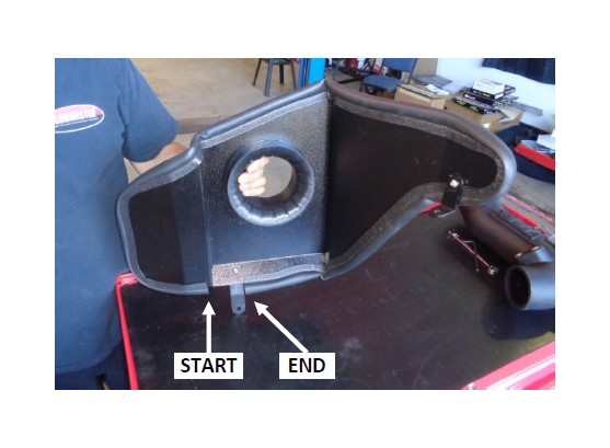
15. Attach gasket (10) to heat shield. Starting at the bend as shown, firmly press the gasket onto the edge, gradually working around the heat shield. When you reach the opposite side of bracket (8), trim the gasket to fit using metal‐cutting shears.
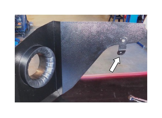
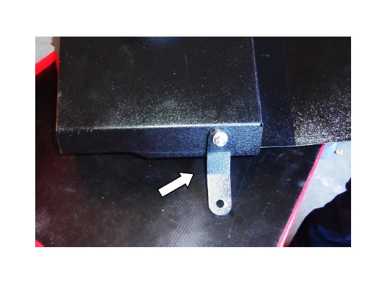
16.Install the assembled heat shield in the vehicle using the stock bolt at the upper bracket (A), and the M8 bolt (15), lock washer (14) and flat washer (13) at the lower bracket (B). Lastly, tighten both brackets to the heat shield at this time.
17.Push the vinyl cap (11) onto the resonator.
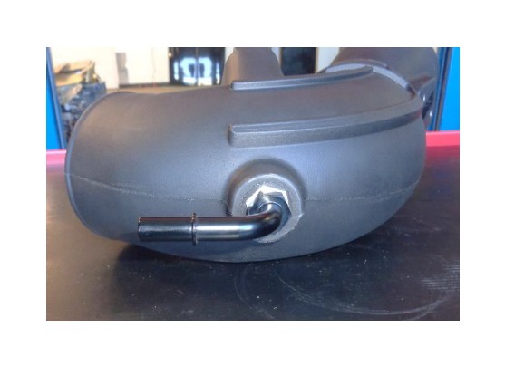
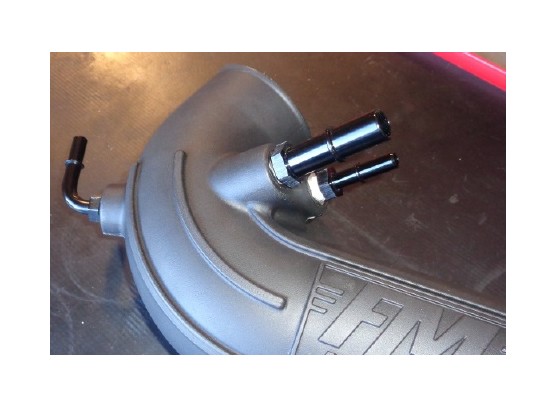
18.Apply 2 wraps of nylon thread tape to the 3/8" quick disconnect (QD) elbow (26), and install it in the intake tube (24). Align the elbow with the tube’s mold line as shown.
19.Apply 2 wraps of nylon thread tape to the 5/8" QD fitting (25) and the 3/8" QD fitting (22), and install them in the intake tube as shown. NOTE: For best hose alignment, we have located the 5/8" fitting above the 3/8" fitting (which is opposite the stock setup).
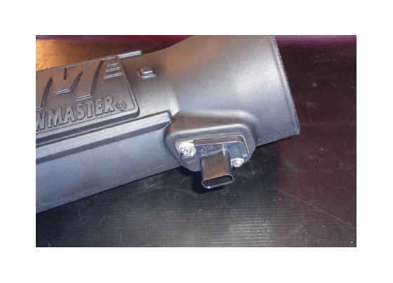
20.Install the MAF sensor gasket (21) onto the sensor, ensuring correct orientation. Then install the sensor in the intake tube, using M4 screws (23).
21.Install the two smaller hose clamps (28) on the smaller coupler (27), and install the coupler on the throttle end of the intake tube. Do not tighten clamps at this time.
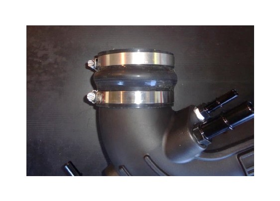
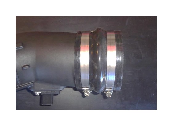
22.Install the two larger hose clamps (19) on the larger coupler (20), and install the coupler on the filter end of the intake tube. Do not tighten clamps at this time.
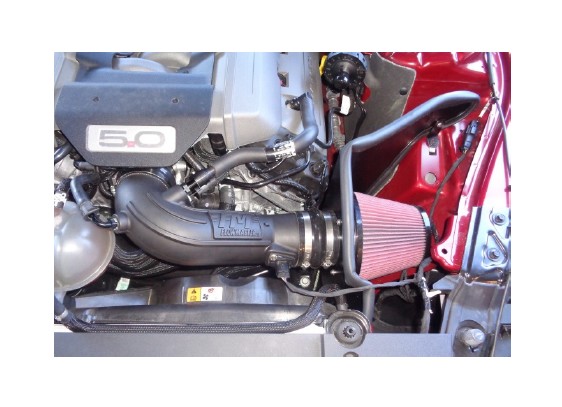
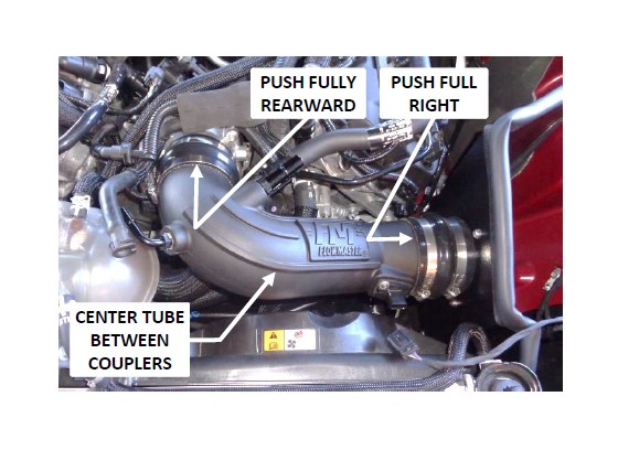
23.Install the intake tube in the vehicle. Push the left coupler up against the raised stops on the throttle body. Push the right coupler up against the heat shield. Then center the intake tube between the couplers, and tighten all hose clamps.
24.Install the MAF sensor plug on the sensor, and push the locking tab toward the sensor. Then check the plug for security.
25.Connect the brake aspirator line (A), the PCV line (B) and the EVAP line (C) to their respective fittings and check for security.
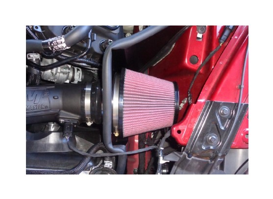
26.Place the clamp (2) on the air filter (1), install the filter on the filter adapter and tighten the clamp.
27.Reinstall the engine cover.
Congratulations, the installation of your FLOWMASTER cold air intake kit is now complete!