FREE 1 to 3-Day Delivery on Orders $149+ Details
How to Install a Ford Racing Tachometer w/ Shift Light on Your 1979-2012 Mustang
Installation
Parts Included:
- 1 - Tach Adapter 9117
- 1 - Butt Connector
- 3 - Mounting Screws
- 2 - Bullet Connectors
CAUTION!!! The Tach Adapter cannot be used with a Capacitive Discharge Ignition (such as an MSD Ignition Control). The voltage on the coil positive must be below 18 volts.
Installation
The Auto Meter Tach Adapter wires in line on the positive 12 volt supply wire. It senses current on the coil positive wire and converts it to a 12 volt signal output. To install the Tach Adapter, the coil positive wire must be identified for your application. Once the wire has been located it is recommended to check for 12 volts using a volt meter. Connect the meter and turn the ignition On. In some cases, the engine must be cranked over in order to see 12 volts. The Tach Adapter is designed to be mounted under the hood. The circuits are potted in polyurethane for water resistance and vibration protection. Position the Tach Adapter away from excessive heat sources and mark the locations of the three mounting holes. Use a 5⁄32” bit to drill holes and secure the unit with the supplied screws.
Route the wires away from direct heat sources, moving components, and sharp edges. Use the supplied bullet terminals on the 12 volt coil wire. (These terminals are supplied so the wiring can be returned to stock if ever desired.) The butt splice crimp connector is used for the Gray tach output lead and the tach trigger wire.
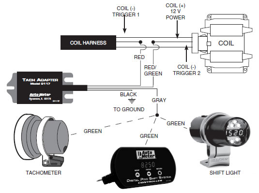
WIRING
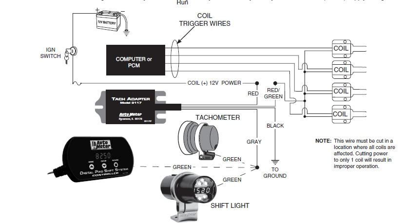
RED - Input, connects to the ignition 12 volt supply coming from the ignition switch.
RED/GREEN - Output, connects to the coil positive wire.
BLACK - Connects to engine ground.
GRAY - Tach output signal wire. Connects to the green Tach trigger wire or other RPM operated component.
Connecting to Coil Per Cylinder (Other Ford cars & Trucks may be the same as below, but with different 42 pin connector location)
Typical ‘99 - 04 Mustang
Locate the large, square 42 pin wire harness connector in the corner of the engine bay where the passenger fender meets the firewall. Pop the plastic cover off the top of this connector to expose where the wires enter the connector and to expose the wire pin numbers. Locate pin number 34 which will be in the corner of this connector. Depending on the specific year and trim of Mustang, the wire color can be Red, Red with a Green stripe, or a White wire with a Blue stripe. Cut this wire in half so that you now have two cut halves. Hook the Red wire of the adaptor to the cut half coming from the connector. Hook the Red/Green of the adapter to the other cut half. Ground the Black wire of the adaptor. The Gray wire of the adapter will now provide you with a good tachometer signal.
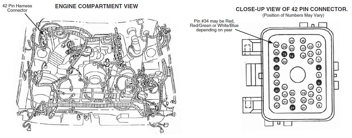
TIP: IT IS EASY TO TRACE THIS WIRE TO A PLACE ON THE PASSENGER SIDE FIREWALL WHERE IT IS EASY TO WORK WITH.

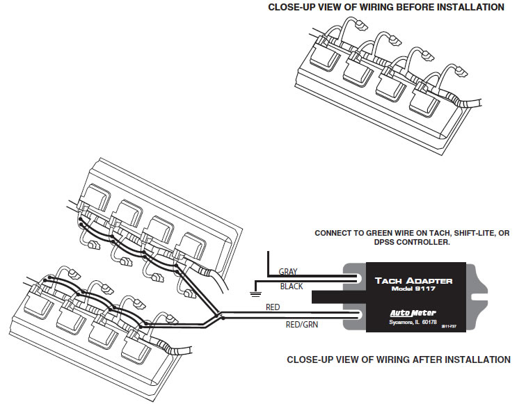
Connecting to a Dodge Hemi with Coil per cylinder ignition.
We recommend only an experienced technician perform this installation. Do NOT attempt, if you are unfamiliar with automotive wiring!
Carefully inspect the wiring at each of the coil packs and note the wire colors at each coil. You will notice that one wire at each coil is different from one to the next, and that one wire is the same color at every coil. The wire that is the same at every coil is your coil power supply. Due to the nature in how the Hemi is wired from the factory, you will need to cut the power wire in half at each coil on both banks of coils. Be sure to leave enough wire at each coil to splice onto later (about 2” works well). After you cut all 8 coil powers, use a 16g wire and link all the power (harness side) cut halves together, then hook to the solid red of the 9117 tachometer adapter. Next, use 16g wire and link all the coil-side cut halves together and hook to the red wire with a green stripe of the 9117 tachometer adapter. Ground the black 9117 adapter wire. The gray wire is your new tachometer signal wire. Set your tachometer as 8 cylinder (4 ppr). All connections should be properly soldered and heat shrunk.
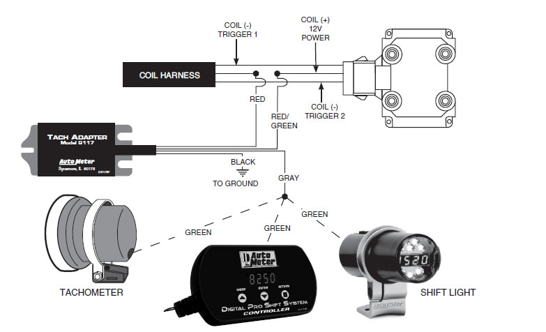
Connecting to GM V-8 W/ C.O.P. Ignition (Vortec and LS-style motors)
Note: It is recommended to have a wiring schematic of your vehicle’s ignition system to clearly identify the Coil Positive (12 volt) supply wiring.
Locate the ignition coil harness connector on each side of the engine. The most common wire color used for power to the coils is Pink. Follow the Pink power wire away from the coils & connector to where it is most comfortable to work with (Auto Meter suggests 2”-6” away), then cut this wire in half. Repeat this on the other side of the engine as well. Run the power-side Pinks (left & right) together and attach to the solid Red of the adapter. Next run the coil-side Pinks (left & right) together and hook to the Red/Green of the Adapter. Ground the Black wire of the adapter to a suitable chassis ground. The Gray wire of the adapter is your new tachometer signal output.

Connecting to a Coil Pack
Note: It is recommended to have a wiring schematic of your vehicle’s ignition system to clearly identify the Coil Positive (12 volt) supply wiring.
Connecting to an Individual Coil Per Plug Ignition System
Note: It is recommended to have a wiring schematic of your vehicle’s ignition system to clearly identify the Coil Positive (12 volt) supply wiring.
Connecting to a Mitsubishi Eclipse and Eagle Talon
Note: It is recommended to have a wiring schematic of your vehicle’s ignition system to clearly identify the Coil Positive (12 volt) supply wiring.